Recording head and information recording apparatus

a recording head and information technology, applied in the field of recording head and information recording apparatus, can solve the problems of reducing the wavelength of light source, the efficiency of emission and numerical aperture cannot be theoretically made larger than 1, and the difficulty of increasing recording density, so as to increase the manufacturing precision of the diffuser, reduce the transition width of magnetization in the magnetic recording layer, and increase the manufacturing precision

Inactive Publication Date: 2006-11-07
HITACHI LTD
View PDF15 Cites 40 Cited by
  • Summary
  • Abstract
  • Description
  • Claims
  • Application Information

AI Technical Summary

Benefits of technology

[0012]As the size of a light spot used for thermomagnetic recording can be reduced without the diffraction limit of an optical system and the limit of the material of an optical component by adopting the above-mentioned configuration, recording density on the recording medium can be increased, and the recording head is extremely advantageous in the size and the cost of an information recording apparatus. Besides, recording can be realized by the consumption of less energy. Further, heat produced by the loss of the diffuser in the recording head can be promptly diffused via the magnetic pole. As a result, the risk of the deterioration and the damage of the diffuser by the rise of temperature is reduced, stress on the vicinity of the diffuser by the heat of the diffuser is minimized and the remarkable enhancement of the reliability of the recording head and the information recording apparatus can be expected.
[0014]As an area in which a temperature gradient by an optical near field is great can be made coincident with an area in the vicinity of the end of the main magnetic pole in which the gradient of a recording magnetic field by recording magnetic field generating means is the greatest by adopting the above-mentioned configuration, the transition width of magnetization in a magnetic recording layer can be reduced and recording density can be increased without increasing the manufacturing precision of the diffuser.

Problems solved by technology

To increase recording density, directly the wavelength of the light source is reduced or the numerical aperture is widened, however, the development of a light source having a shorter wavelength has an extremely great problem in the material of a light source element and the efficiency of emission and the numerical aperture cannot be theoretically made larger than 1.
Therefore, in information recording depending upon the light spot at the diffraction limit, there is great difficulty to increase recording density.
Therefore, it is difficult to stably form a recording mark in size by far smaller than the diameter of the light spot and the solid immersion lens has a limit in increasing recording density.
However, in these prior arts, the metal diffuser that generates an optical near field is exposed at the bottom of the recording slider and has structure that the metal diffuser is in contact with only a dielectric the thermal conductivity of which is relatively low.
Therefore, a problem that when a part of recording energy is absorbed by the metal diffuser, the temperature rapidly rises, the metal diffuser is gradually oxidized, a function as the diffuser is damaged and in the worst case, the diffuser is dissolved and broken exists.
Besides generally, as a dielectric and metal forming the diffuser are greatly different in a coefficient of thermal expansion, great stress is caused on an interface between both, and as possibility that the metal diffuser may peel and fall from the dielectric is high, the realization of a reliable recording head and a reliable information recording apparatus is hindered.
Therefore, unless the distribution size of an optical near field is reduced, the transition width of magnetization cannot be reduced and there is a limit to increase recording density without increasing the manufacuring precision of the metal diffuser.

Method used


Image

  • Recording head and information recording apparatus
  • Recording head and information recording apparatus
  • Recording head and information recording apparatus

Examples


Embodiment Construction

[0021]Referring to the drawings, concrete embodiments of the invention will be described in detail below.

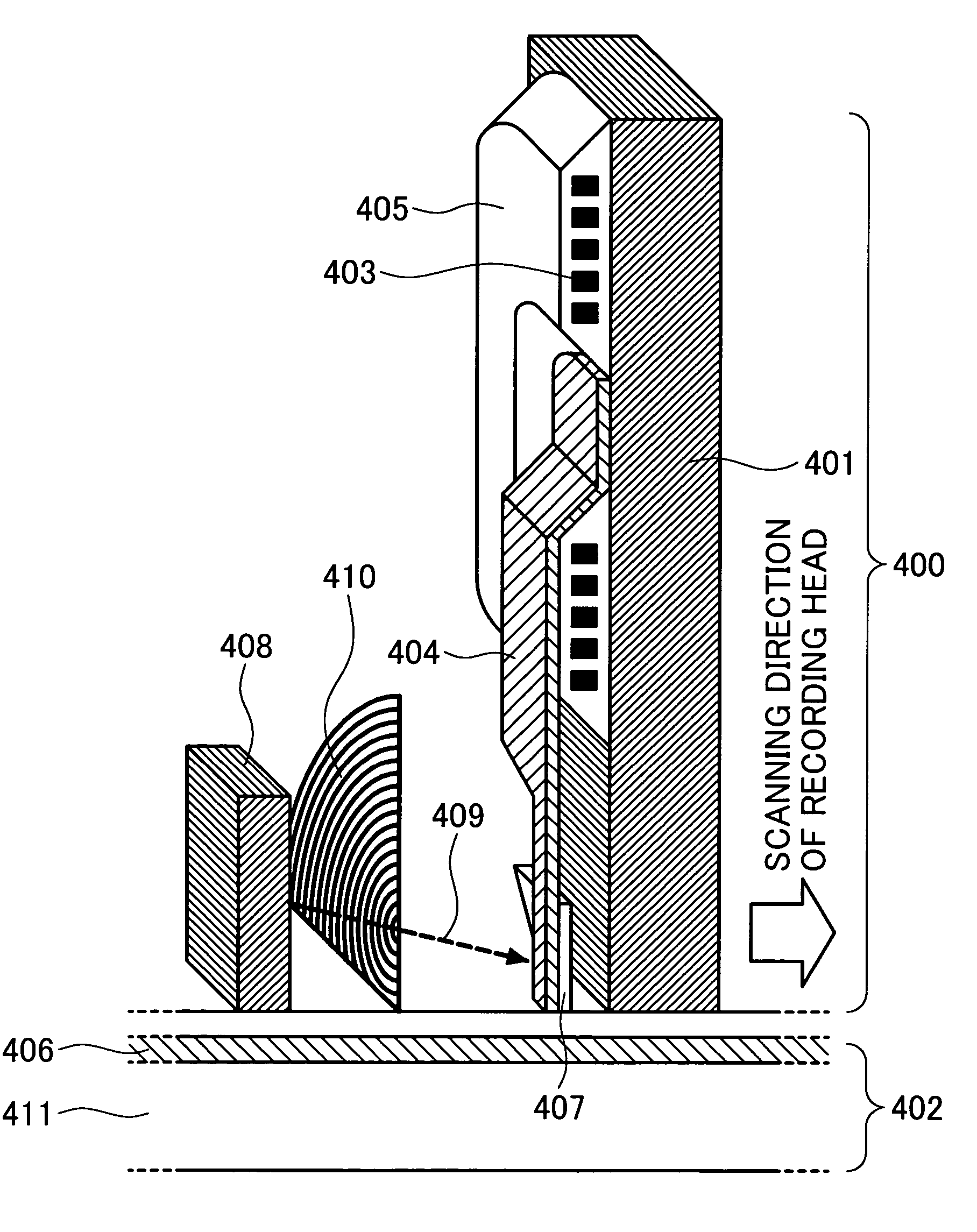
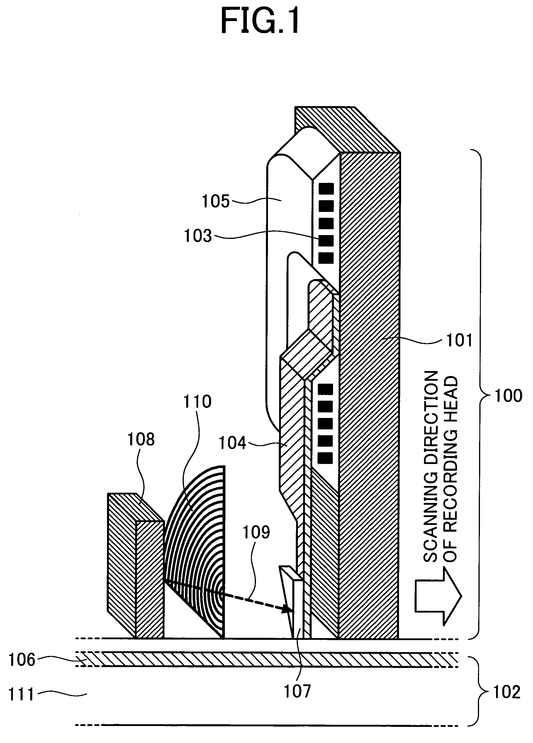
[0022]FIG. 1 shows a first example showing the configuration of a recording head according to the invention and shows the sectional structure of the circumference of a recording mechanism in case the recording head and a recording medium are cut along their faces perpendicular to a surface of the recording medium (in a vertical direction in FIG. 1) and parallel to a scanning direction (a direction of a track which is a lateral direction in FIG. 1). The method of depiction is common in embodiments shown in FIGS. 1 to 4. In the recording head 100, a flat auxiliary magnetic pole 101 is formed so that it is substantially perpendicular to the recording medium 102 and is substantially orthogonal to the scanning direction. Further, a conductive pattern 103 made of copper is spirally formed over the auxiliary magnetic pole 101. An insulator such as aluminum oxide is filled between the co...


PUM

PropertyMeasurementUnit
surface roughnessaaaaaaaaaa
diameteraaaaaaaaaa
refractive indexaaaaaaaaaa

Abstract

To generate a satisfactory recording magnetic domain on a recording medium and to improve the durability of a recording head, an information recording apparatus for generating an optical near field and thermo-magnetically recording information on the recording medium is provided with a light source, a magnetic pole for applying a magnetic field to the recording medium and a diffuser that generates an optical near field in the vicinity of the recording medium when light from the light source is radiated. The diffuser is formed with it in contact with the magnetic pole so that the face which light from the light source irradiates is substantially perpendicular to the recording medium. Thereby, recording density in the information recording apparatus can be increased, simultaneously the reliability can be also enhanced and as a result, the cost can be reduced.

Description

BACKGROUND OF THE INVENTION[0001]1. Field of the Invention[0002]The present invention relates to a recording head provided with a function for optically or thermally exciting a magnetic recording medium, locally reducing the coercivity of the recording medium and thermo-magnetically recording information and an information recording apparatus using it.[0003]2. Description of the Related Art[0004]In Japanese published unexamined patent application No. Hei10-162444, “Magneto-optical recording medium, recording / reading method and recording / reading apparatus” (first prior art), technique utilizing a head using a solid immersion lens in a recording / reading apparatus for recording a hyperfine magnetic domain signal at a hyperfine light beam spot on a magneto-optical disk is disclosed.[0005]Besides, in Japanese published unexamined patent application No. 2001-255254, “Optical near field probe, optical near field optical microscope using it and optical recording / reading apparatus” (second p...

Claims


Application Information

Patent Timeline
Patent Type & Authority Patents(United States)
IPC IPC(8): G11B5/02G11B11/00G11B11/10G11B5/00G11B5/127G11B5/39G11B7/135G11B7/1387G11B11/105
CPCB82Y10/00B82Y25/00G11B5/00G11B5/127G11B5/1278G11B5/3909G11B7/1387G11B11/10536G11B11/10554G11B5/02G11B5/3967G11B2005/0002G11B2005/0005G11B2005/001G11B2005/0021G11B2005/0029G11B2005/3996G11B5/314G11B5/6088
Inventor SAGA, HIDEKIMATSUMOTO, TAKUYAISHIKAWA, KEISUKEDA, HIROFUMI
Owner HITACHI LTD
Why Eureka
Try Eureka