Method and apparatus for selective deep catalytic cracking of hydrocarbons

a deep catalytic cracking and hydrocarbon technology, applied in hydrocarbon preparation catalysts, hydrocarbon oil treatment products, bulk chemical production, etc., can solve the problems of inflexible steam cracking technology to respond to these or other market trends, and achieve the effect of increasing the total conversion of n-hexane and increasing the yield of light olefins

Inactive Publication Date: 2006-11-14
VALORBEC PARTNERSHIP
View PDF3 Cites 14 Cited by
  • Summary
  • Abstract
  • Description
  • Claims
  • Application Information

AI Technical Summary

Benefits of technology

[0022]In operation, the feed comprising the hydrocarbons to be cracked and steam, in well-defined proportions, is first sent into a pre-catalytic zone (Zone I) of a steam cracking reactor, preferably a tubular reactor. In a preferred embodiment, Zone I, contains beads of some catalytically mildly active porous material such as quartz or quartz doped with Cr—Al, is set at a temperature T1. The gas stream flows then through a catalyst bed, called Zone II, where the catalytic reaction takes place. Zone II is set at temperature T2 and contains a zeolite type catalyst, preferably Z...

Problems solved by technology

However, currently available steam cracking technology is not sufficiently flexible to respond to these or other market trends.
(a) enhanced production of commercially valuable produc...

Method used


Image

  • Method and apparatus for selective deep catalytic cracking of hydrocarbons
  • Method and apparatus for selective deep catalytic cracking of hydrocarbons
  • Method and apparatus for selective deep catalytic cracking of hydrocarbons

Examples


example

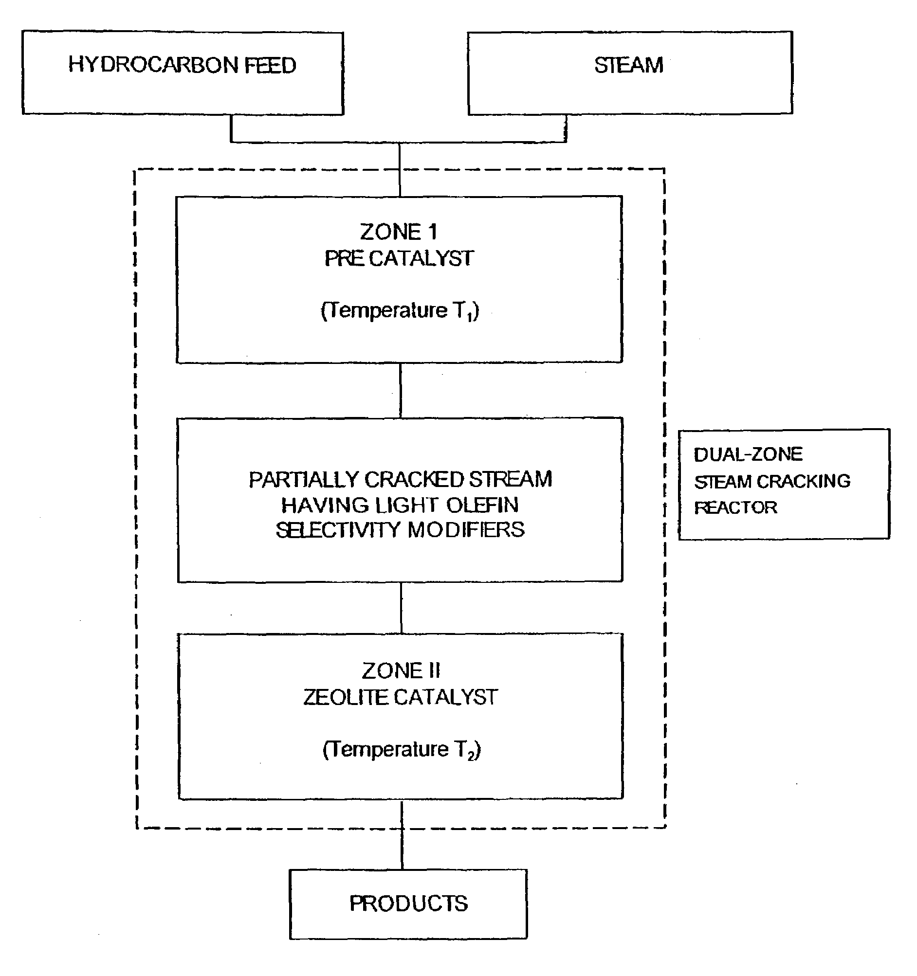
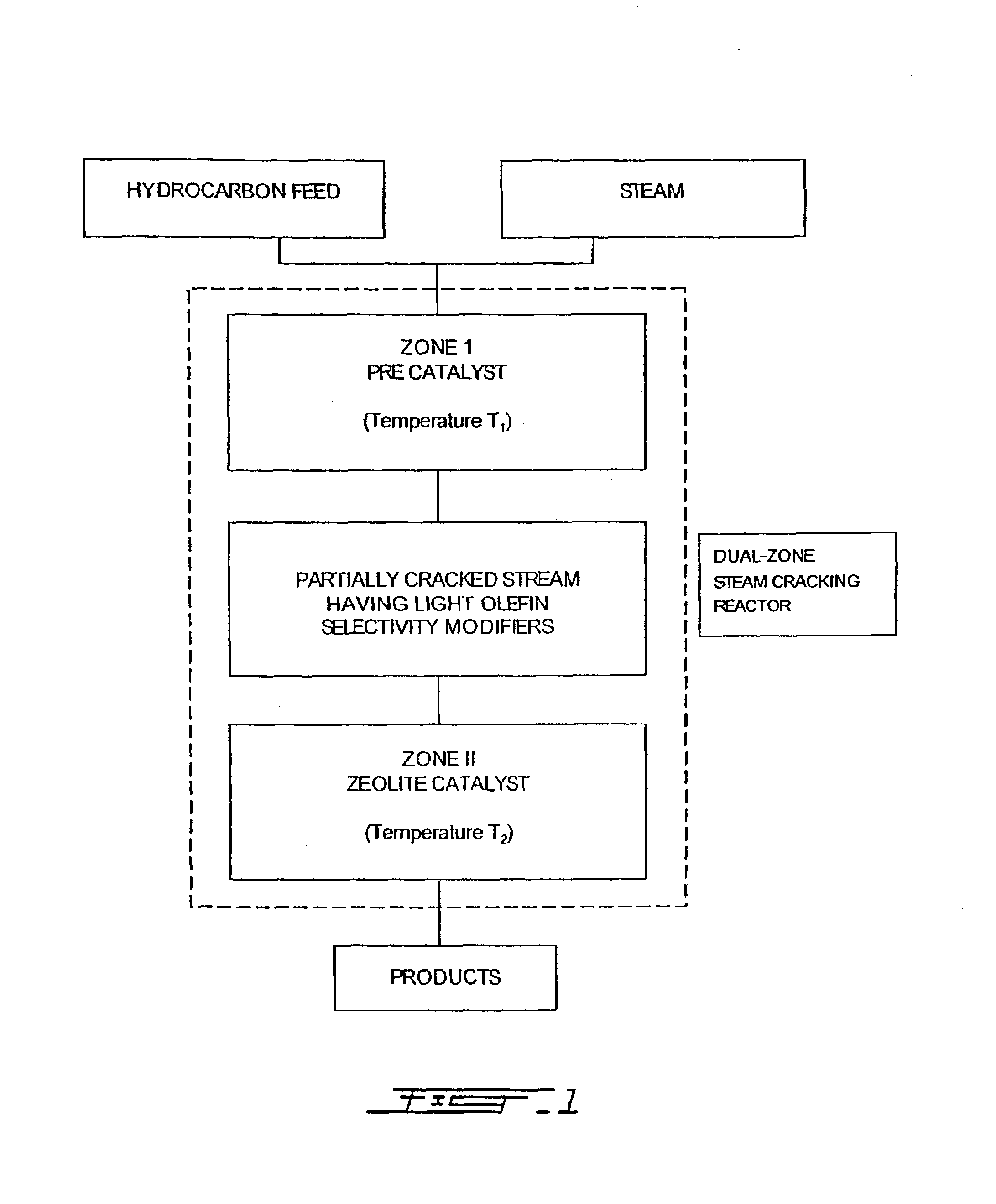
[0033]An example of the method of the present invention will now be described in relation to the catalytic steam cracking of n-hexane (used as a model molecule for petroleum naphthas). Although the present invention has been experimentally demonstrated based on n-hexane, this is an excellent model molecule for predicting the behaviour of other hydrocarbons, in particular longer chain hydrocarbons and their mixtures such as the ones found in petroleum naphthas, since the catalytic behaviors of these feeds are analogous.

[0034]N-hexane when sent together with some steam through Zone I, undergoes partial steam-cracking and dehydrogenation. The products of this conversion include olefins and diolefins which are known to increase—by hydrogen transfer or olefin dissociation—the selectivity towards light olefins during the reaction over zeolite based catalysts.

[0035]The probable light olefin selectivity modifiers generated in Zone I and affecting the activity and selectivity of the zeolite ...


PUM

PropertyMeasurementUnit
Temperatureaaaaaaaaaa

Abstract

Provided herein is a method and apparatus for selective deep catalytic cracking of petroleum naphthas or other hydrocarbon feedstocks. The feed comprising the hydrocarbons to be cracked and steam, in well-defined proportions, is first sent into a precatalytic zone (Zone I) of a cracking reactor, preferably a tubular reactor. In a preferred embodiment, Zone I, contains beads of some catalytically mildly active porous material such as quartz or quartz doped with Cr—Al, is set at a temperature T1. The gas steam flows then through a catalyst bed, called Zone II, where the catalytic reaction takes place. Zone II is set at temperature T2 and contains a zeolite type catalyst, preferably ZSM5 zeolite or, most preferably, a hybrid zeolite catalyst. It is shown that by moderately increasing the temperature T1 of Zone I, it is possible to have an increased total conversion of n-hexane used as model molecule for petroleum naphthas and an increased yield of light olefins (and aromatics), when compared to the parent ZSM-5 zeolite catalyst The ethylene/propylene product ratio is closely dependent of the temperature T1, if all other reaction parameters are kept constant and can be widely varied (from 1.0 to 2.0 for instance) for a limited range of variation of temperature T1.

Description

BACKGROUND OF THE INVENTION[0001]1. Field of the Invention[0002]The present invention relates to a method and related apparatus for catalytic steam cracking of hydrocarbons.[0003]2. Description of the Prior Art[0004]Steam cracking of hydrocarbons is one of the core processes in the petrochemical industry. Current world production of stream cracking products is estimated to reach 100 million metric tons / year of ethylene and propylene.[0005]Basically, steam cracking comprises a step in which the hydrocarbon mixture to be transformed is mixed with steam and submitted to elevated temperatures in a tubular reactor, usually in the presence of one or more catalysts. The reaction temperature usually ranges from 700 to 900° C. according to the type of feedstock treated (the longer the hydrocarbon molecular structure, the lower the required temperature for cracking) while the residence time ranges from a few seconds to a fraction of second. The different resulting products, gaseous or liquid ...

Claims


Application Information

Patent Timeline
IPC IPC(8): C07C4/02
CPCC07C4/06C07C2529/40C07C2529/48C10G2400/20Y02P20/52C07C11/04C07C11/06
Inventor LE VAN MAO, RAYMOND
Owner VALORBEC PARTNERSHIP
Why Eureka
Try Eureka