
Device for determining the composition of a fluid mixture

a fluid mixture and composition technology, applied in the direction of fluid resistance measurement, resistance/reactance/impedence, instruments, etc., can solve the problems of increasing instrument error, erroneous data, and significant water concentration measurement errors

Active Publication Date: 2006-11-14
KAM CONTROLS
View PDF22 Cites 68 Cited by
  • Summary
  • Abstract
  • Description
  • Claims
  • Application Information

AI Technical Summary

Benefits of technology

"The patent describes a method and device for measuring the concentration of individual components in a fluid mixture. The device includes a sensor probe with two sensors, one for measuring parameters and one for detecting anomalies. Compensation factors are applied to the measured parameters to account for the anomalies, and the calculated permittivities of the components are then used to determine their concentration in the fluid mixture. The device is controlled by a microcontroller and can measure multiple parameters simultaneously. The technical effect is a more accurate and reliable method for measuring the concentration of fluid components."

Problems solved by technology

However, several perturbing factors adversely influence currently available measurement means to yield highly erroneous data.
An unknown salt concentration typically gives rise to significant errors in the measurement of water concentration in a hydrocarbon fluid mixture.
However, if the salt concentration varies over time, instrument error will be increased unless there is active compensation for the varying influence of the salt.
Likewise, interactions between sulfur compounds and the water in a hydrocarbon fluid mixture will adversely influence the accuracy of the measurement of water concentration in the fluid mixture.
Increasing the number of components significantly, however, adds to the problem.
Thus, as the oscillator frequency is changed, the complex permittivity also changes and the resulting system of mathematical equations used to describe and solve for the component concentrations become increasingly non-linear.
As with any electronics, these oscillators are subject to drift due to the temperature of the ambient surroundings or from self-heating and aging of the components.
It is difficult, or impossible, to separate drifts in the oscillator from actual impedance changes in the fluid medium; and, as explained previously, non-linear dielectric constants tend to magnify the measurement errors.
Some systems include a reference oscillator calibrated to provide a specific frequency for a known impedance, but the reference oscillator is subject to the same thermal and aging errors.
Thus, the reference and measurement oscillators require frequent calibration and recalibration.
In this system the reference capacitor will only compensate for the measuring circuit drift and aging, but not the pressure and temperature of the oil and water mixture.
The single operating frequency of the unit is 50 kHz, rendering the unit incapable of dealing with variations in the measurement due to variations in salt and sulfur compounds.
Nevertheless, the measurement accuracy will be affected when there are changes in either oil composition or in water salinity of the actual mixture being measured.
The single frequency measurement of this device is unable to ascertain the effects of varying concentrations of salt or sulfur compounds in the fluid mixture.
Single frequency capacitance apparatuses have not been successful in measuring the water content of the hydrocarbon in high concentrations because salt, sulfur, density, and temperature adversely influence the capacitance reading.
However, optical apparatuses have not proven effective for midrange water concentrations.
This type of device also requires extensive periodic recalibration, and measurement errors increase as the optical sources and / or sensors become dirty, as is often the case in oilfield applications.
None of the apparatuses disclosed or currently available are able to self-calibrate, automatically select and switch the frequency range, find the optimum frequency, and / or make rapid multiple measurements to accurately measure oil and water mixture ratios, salt and sulfur content, as well as the density of the fluid mixture.

Method used


Image

  • Device for determining the composition of a fluid mixture
  • Device for determining the composition of a fluid mixture
  • Device for determining the composition of a fluid mixture

Examples


first embodiment

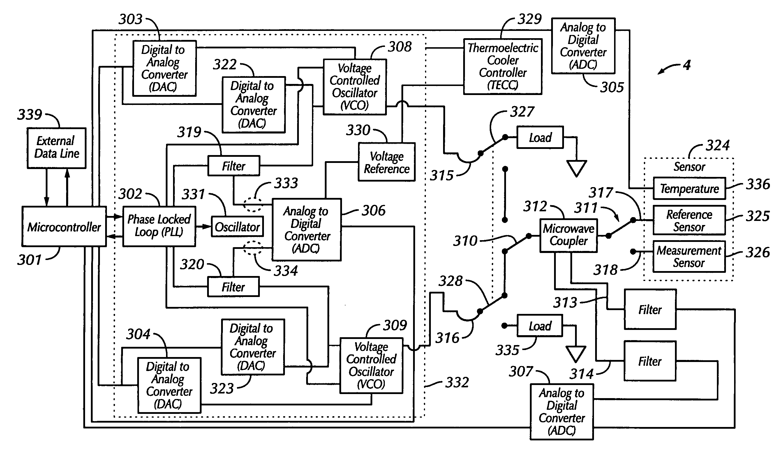
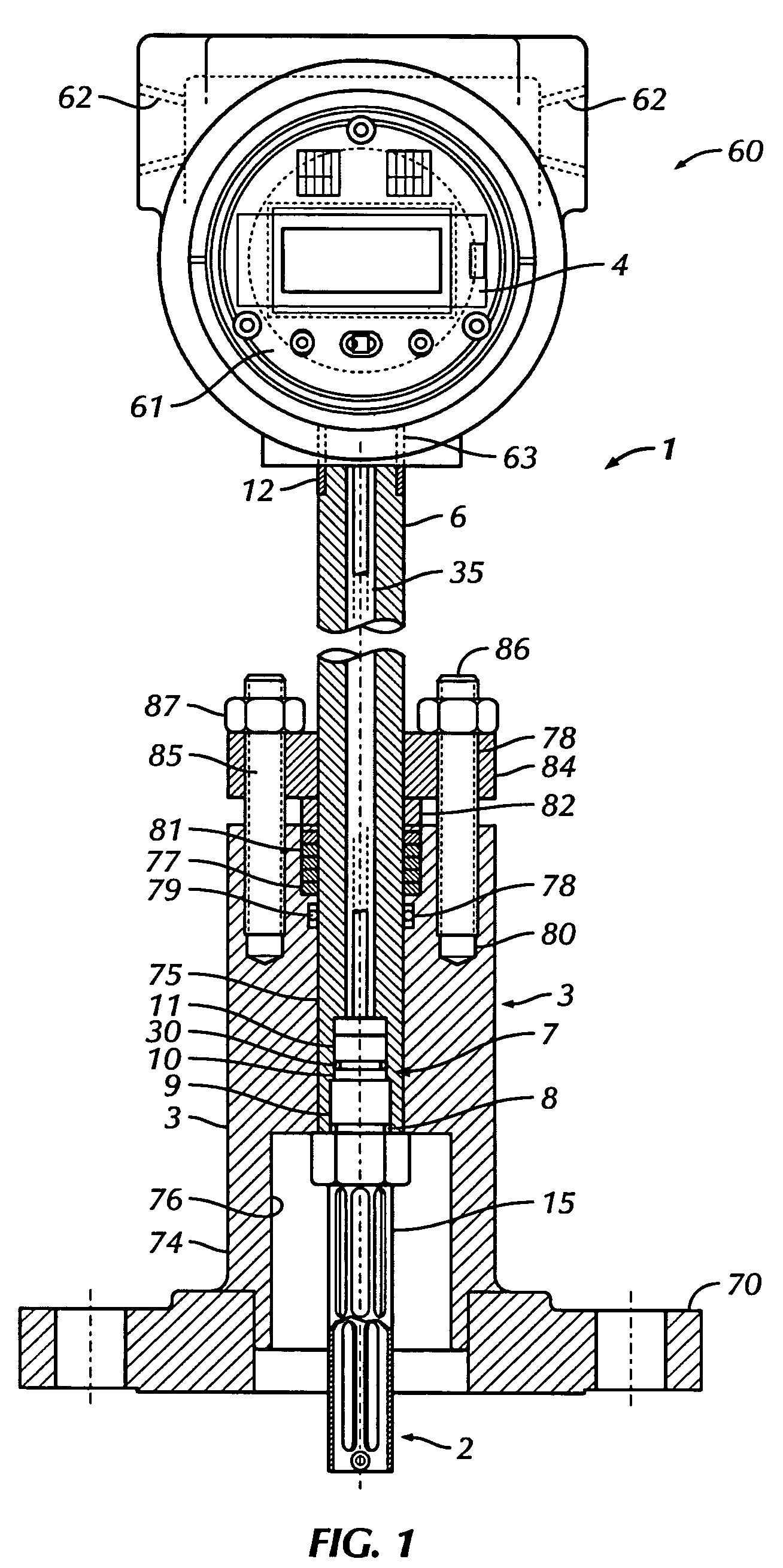
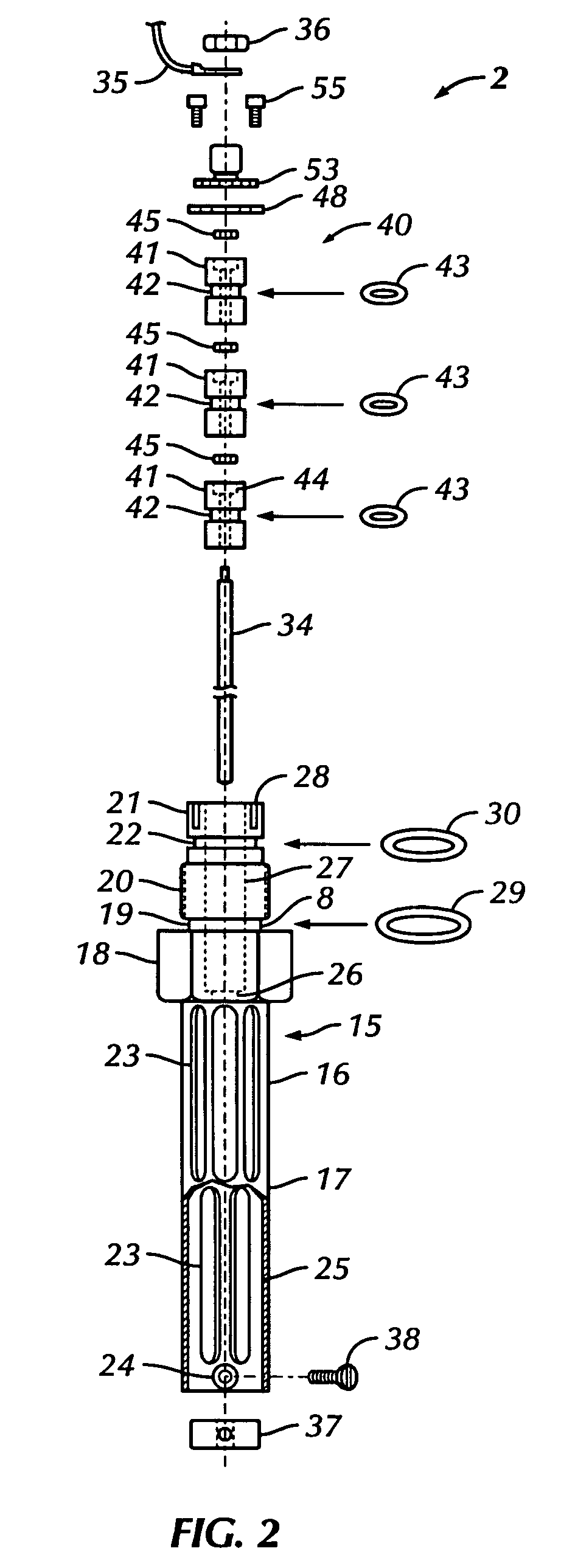
[0055]a sensor device 1 of the present invention is shown in FIGS. 1, 4 and 5. The sensor device 1 is configured for flange mounting on a fluid conduit (such as a pipeline 201 shown in FIGS. 4–5) provided with a co-mating flange. Typically, a probe 2 of the sensor device 1 is radially inserted into a flow stream confined within a circular tubular conduit, such as a tank or pipeline 201.

[0056]The flow conduit is provided with a radial circular port either by having a welded mounting flange preinstalled with the port during fabrication or by being hot-tapped in service with a conventional hot-tap fitting and machine used to produce a port. In the latter case, the mounting flange is mounted on the outer end of the hot tap fitting or, alternatively, on a valve on the outboard end of the hot tap fitting. An example of a suitable hot tap fitting and hot tap machine would be the IPSCO Flostop II system, provided by the International Piping Services Company, Broadview Ill. 60153. The materi...

embodiment 630

[0091]In this embodiment 630, identical electrode rods 670 are used. Each electrode rod 670 is an elongated right circular cylinder made of conductive metal and having at its connector end a male thread engageable by a hex nut 671 and an intermediate transverse flange adjacent the thread. As an alternative, the flange can be omitted and replaced by a second hex nut 671. Each electrode rod 670 is inserted through the center hole in installed electrode holder 651 or 655 and its nut 660 tightened so that flow past the electrode holder 651 or 655 is stopped by its O-ring 657 and flow past the electrode rod 670 is stopped by its O-ring 666. In this manner, each of the electrode rods 670 is caused to extend into the pressure containing body assembly 631 of the sensor device 630. A crimp-on ring wire terminal 674 with an attached wire 675 is clamped to the threaded end of each electrode rod 670 by a nut 671 to effect electrical connection between the rod 670 and the system electronics (not...


PUM

PropertyMeasurementUnit
frequencyaaaaaaaaaa
operating frequencyaaaaaaaaaa

Abstract

A method and apparatus are disclosed for determining the concentration of individual components within a fluid mixture by determining the permittivity of the individual components. The method and apparatus use a reference sensor and at least one measurement sensor positioned inside the same sensor device that is immersed in the fluid mixture to be measured. Signals, such as radio frequency or microwave, are sequentially transmitted at multiple, known, constant frequencies to and reflected from both the reference and measurement sensor(s). Permittivities of the individual components are determined from these transmitted and reflected signals and information about the concentration of the individual fluids and other compounds within the fluid mixture and the density of the fluid mixture are produced. Repetitive sampling and processing of these signals allow determination and real-time monitoring of the concentration of individual components within a mixture of fluids. The present invention provides self-calibration, accurate frequency maintenance and self-selection of an operating frequency range.

Description

CROSS REFERENCE TO RELATED APPLICATIONS[0001]This application claims priority to pending U.S. Patent Application Ser. No. 60 / 567,838 filed May 4, 2004 by inventors Kim Mohajer, Ed Browne and Abbas Khajeh and entitled “Device for Determining Composition of Fluid Mixture”.BACKGROUND OF THE INVENTION[0002]1. Field of the Invention[0003]The present invention relates in general to a method and apparatus for determining the concentration of components (such as water, oil, salt and sulfur) in a fluid mixture. More particularly, the present invention relates to a method and apparatus for determining the concentration of individual components within a mixture of fluids by utilizing the permittivity of the individual components when the permittivities of the different components are measurably distinct.[0004]2. Description of the Related Art[0005]Knowledge of accurate water content, salt content, sulfur content, and density of the hydrocarbon and chemicals for a fluid mixture is important for...

Claims


Application Information

Patent Timeline
Patent Type & Authority Patents(United States)
IPC IPC(8): G01R27/04G01N22/00G01N30/62G01N30/95G01N33/20G01N33/28G01N37/00G01R27/08G01R27/22G01R27/26G01R27/32
CPCG01N22/00G01N33/2847G01R27/22
Inventor MOHAJER, KIMBROWNE, EDWARD MCCHESNEYKHAJEH, ABBAS
Owner KAM CONTROLS
Learn More