Method and apparatus for beam deflection

a beam deflection and beam technology, applied in the direction of optics, mountings, instruments, etc., can solve the problems of device power consumption continuous, large number of channels needed for optical switching, and additional complexity and cos

Inactive Publication Date: 2006-11-14
THE GSI GRP LLC +1
View PDF60 Cites 29 Cited by
  • Summary
  • Abstract
  • Description
  • Claims
  • Application Information

AI Technical Summary

Benefits of technology

[0020]Several problems of the prior art are solved by the present invention as will be readily apparent from the examples and drawings listed below. Other and various objectives a

Problems solved by technology

With the development of digital wavelength division multiplexing (DWDM), the number of channels needed for optical switching can become very large.
These devices require continuous consumption of power, to maintain the position.
This power generates heat that must be cooled and the total power load must be backed up in case of disruption, with battery and generator systems causing additional complexity and cost.
Such an arrangement provides a poor packing density for each device leaving a low mirror area to total area ratio.
One problem with the device shown in FIGS. 1A and 1B is that the mirror is surrounded mainly by air and lacks any conductive path to remove heat.
This is one reason that conventional MEMS mirror devices are limited to low power, e.g. only 31 mw in the above example.
MEMS mirrors are also thin and subject to surface distortion caused by thermal stress such as may result from the heat absorbed by the substrate and by the always-on actuators.
Other surface distorting factors include mechanical forces developed during actuation and release of actuation and even sagging due to the MEMs mirror low stiffness.
Vibration and shock loads may also lead to transient mirror surface distortion.
Mirror surface distortions may cause beam distortions, e.g. wave front aberration, scattering and optical pow

Method used


Image

  • Method and apparatus for beam deflection
  • Method and apparatus for beam deflection
  • Method and apparatus for beam deflection

Examples


Embodiment Construction

[0051]It should be stated at the outset that the invention is susceptible of many embodiments and is applicable to other and various uses where dynamic control of the directional orientation from a reference point, of a very small platform or device is needed, particularly with little or no power required to hold a desired position once acquired. What follows is merely a description of a preferred embodiment, and should not be construed as limiting of the scope of the invention.

Ball and Socket

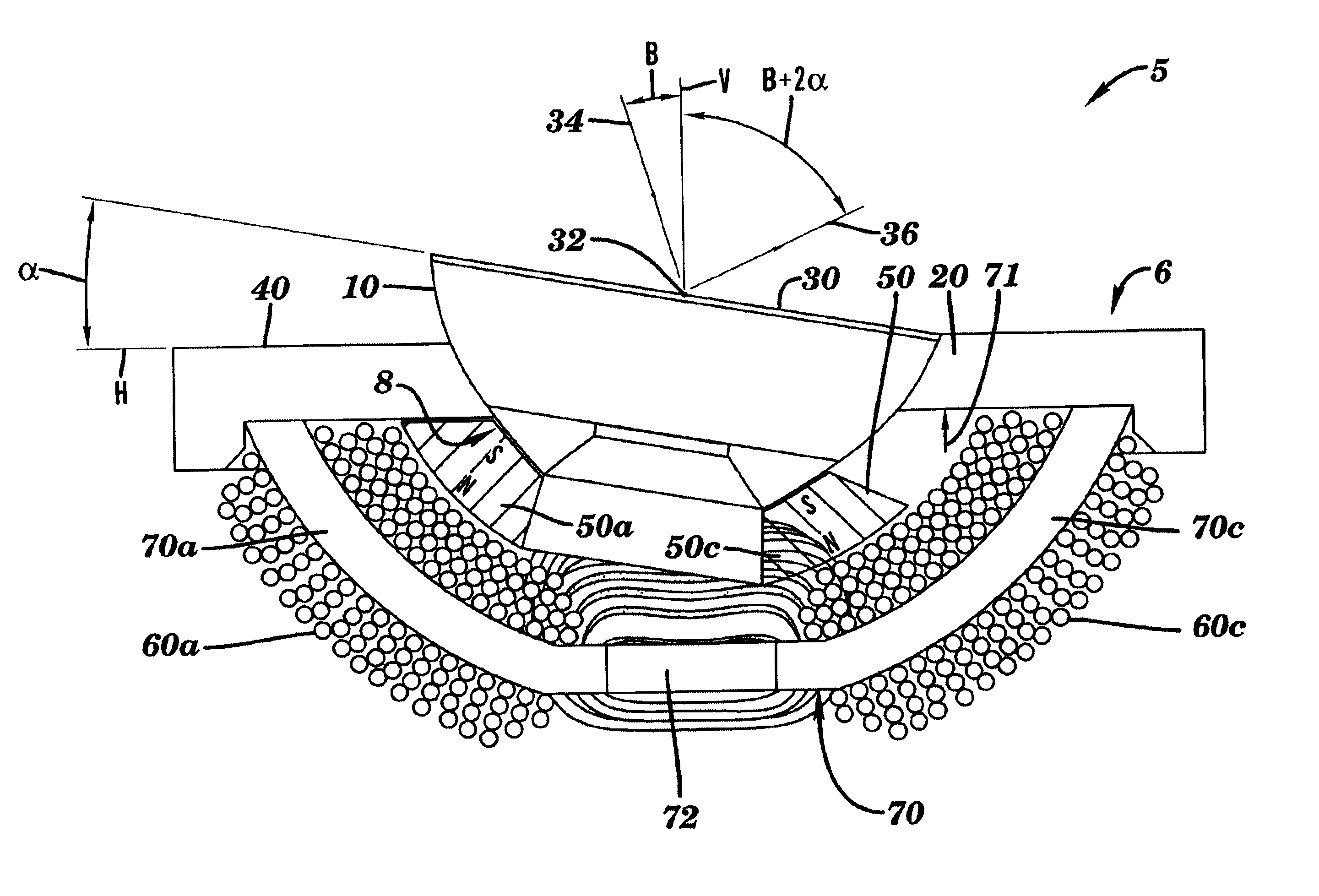
[0052]Referring now to FIGS. 3A-6, there is illustrated the general layout of a preferred embodiment of the invention. FIG. 3A depicts a sectional view showing a two axis optical beam steering apparatus 5 in the general form of a ball and socket assembly. It is comprised of a movable member 10 in the form of a spherical or ball portion having an outer bearing surface 11 supported in a fixed member 40 that includes a spherical raceway or socket 20 for forming a seat in which the movable member 1...


PUM


Abstract

The invention provides a method and apparatus for directing a radiation beam (504, 606) in a desired direction. There is provided a movable member (10) supported for movement by a fixed member (40) and the movable member has an optical element, e.g a flat mirror (30) fixedly attached thereto. In one embodiment the mirror scans a radiation beam incident thereon in one plane. In a second embodiment, the radiation beam is scanned in two mutually perpendicular planes. A magnetic element (50) having a north and a south magnetic pole is fixedly attached to the movable member (10). A magnetically permeable stator element (70) that is stationary with respect to the movable member (10) and the magnetic element (50) is placed in the field of the magnetic element such that the stator element and said magnetic element mutually generate a magnetic traction force between them. A current coil (60) is wound around a portion of the stator element (70) and a current driver (400) is provided for driving a current in the current coil (60). The current induces an electromagnetic force in the stator element (70) and the electromagnetic force acts on the magnetic element (50) for controlling movement of the optical element (30) with respect to the fixed element (40). A radiation beam source (502) may be directed onto the movable mirror surface (30) and scanned by the movement of the mirror to direct the radiation beam in a desired propagation direction. Alternately, a radiation source (604) may be attached to the movable member (10) and pointed in a desired direction.

Description

[0001]This application relates and claims priority for all purposes to pending U.S. application Ser. No. 60 / 280,232, filed Mar. 30, 2001, and related U.S. applications entitled Apparatus for Controlled Movement of an Element, application Ser. No. 10 / 075,940, and Free Space Optical Switch, application Ser. No. 10 / 075,946, both filed on even date herewith and commonly assigned.FIELD OF INVENTION[0002]The present invention relates to a mechanism for directing an optical beam in free space by controlled angular movement of an optical element in one or two dimensions. In particular the invention relates to a beam steering device for use in a free space Optical Cross connect (OCX) switch used in a fiber to fiber telecommunications switching application or in an optical beam scanning apparatus for directing a beam in a desired pattern of movement.BACKGROUND OF THE INVENTION[0003]In fiber-optic communications there is a need for optical switching of light signals from fiber to fiber for pat...

Claims


Application Information

Patent Timeline
IPC IPC(8): G02B6/26G02B6/35G02B26/08
CPCG02B6/3572G02B26/0816G02B26/105G02B6/3518G02B6/3556G02B6/3584G02B6/359G02B7/1828
Inventor BROWN, DAVID C.STUKALIN, FELIXNUSSBAUM, MICHAEL B.ONOICENCO, EVGHENIIKELLEY, EDWARD L.
Owner THE GSI GRP LLC
Why Eureka
Try Eureka