Microflow system for particle separation and analysis

a microflow system and particle technology, applied in the field of particle separation, sorting, sorting, and particle detection, can solve the problems of high dilution of desired cell samples, low speed and sterility, and cell sorting by flow cytometry suffers, etc., to achieve the highest resolution of detection, easy integration, and high sensitivity to susceptibility.

Inactive Publication Date: 2006-11-21
INVERNESS MEDICAL SWITZERLAND GMBH
View PDF24 Cites 74 Cited by
  • Summary
  • Abstract
  • Description
  • Claims
  • Application Information

AI Technical Summary

Benefits of technology

[0075]It is an important advantage of the present invention that a micro flow system is provided that operates continuously with no requirement for operator intervention.
[0076]It is another advantage of the present invention that separation may be performed in one step.
[0077]It is still another advantage of the present invention that the particles can be separated in a continuous flow without substantially interfering with the flow itself and that separated particles may be collected at corresponding separated outlets of the flow channel without having to interrupt the flow in the flow channel.
[0078]It is another important advantage of the invention that the particles contained in the sample by the adjustment of the flow rate of one or more guiding buffers can be lined up in one row such that the particles can be analysed and sorted individually. This results in a sorting system with the highest sensitivity to the susceptibility of the single particle to the field applied to the sorting channel and a sorting system with the highest resolution of the detection means of the characteristics exhibited by the particles.
[0079]It is yet another advantage of the present invention that the micro flow system is easily integrated into other continuous flow systems, such as flow cytometers, flow injection analysis systems, etc.
[0080]It is a further advantage of the present invention that particles may be separated into a plurality of groups of particles, e.g. different subpopulations of cells, based on different susceptibility to the field generated across the flow channel of the different groups of particles. This may be obtained by using a multiple outlet micro flow system as outlined in FIG. 5(c).

Problems solved by technology

However, cell sorting by flow cytometry suffers from several drawbacks, especially high dilution of desired cell sample, low speed and sterility problems.
Furthermore, the equipment is very costly with high operation and maintenance cost, making the technique available only to a limited number of laboratories.
Although this method offers relatively inexpensive approach to sort rare cellular event, it adds considerable time onto the overall rare event detection and it does not offer the multiparameter analysis readily available with flow cytometry techniques.
Existing techniques for magnetic separation are suffering from the low purity of the sorted cell fraction and the low recovery rate of the sorted cells.
In most systems several washing steps have to be implemented into the separation procedure which then causes cell losses.
Additionally small subpopulation of labelled cells cannot be directly isolated by existing magnetic separation techniques.

Method used


Image

  • Microflow system for particle separation and analysis
  • Microflow system for particle separation and analysis
  • Microflow system for particle separation and analysis

Examples


example 2

[0184]Further, the micro flow system used in Example 1 has also been tested by utilising it for separation of Human T-lymphocytes (JURKAT cells). Magnetically stained and unstained JURKAT cells were used to form a heterogeneous cell sample. For magnetic staining of the cells, a CD4-magnetic surface marker from Miltenyi Biotech was used. JURKAT cells were suspended in 1% PBS / BSA to a concentration of 107 / ml. Biotin-conjugated CD4 magnetic microbeads were added at 2 μl stock / 107 cells following the manufacturer instruction.

[0185]The magnetically stained cells (107 cells / ml) flowed through the microchip for 10 min. and fluids were collected at the two outlets. Three experiments at different flow rates (5, 25, 50 μl / min) were performed. The same experiments were performed using magnetically unstained cells.

[0186]An aliquot of the collected samples was analysed under a microscope and the particles were counted using a Neubauer microscopy chamber. For each experiment 1 μl sample was analy...

example 3

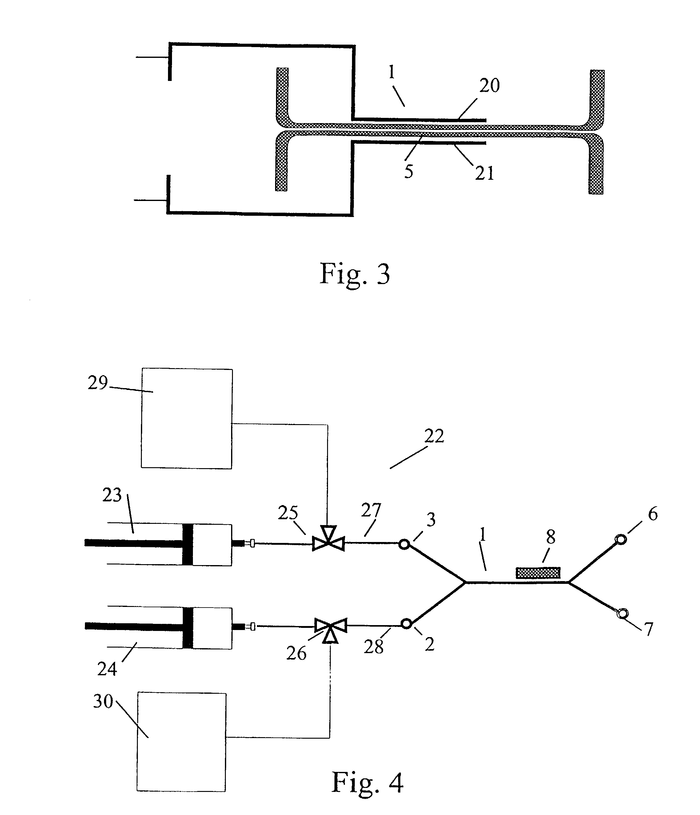
[0188]The system employed for separation of magnetisable particles from a sample is shown in FIG. 4. It comprises two syringe infusion pumps (Harvard Apparatus, Southnatik, Ariz.) that provides constant flow rates of 0.1 to 100 μl / min using a 0.5 ml micro syringe (Hamilton, Bonaduz, Switzerland), a separation flow channel of silicon for the separation of the magnetisable particles, and a collecting unit for collecting of the sorted particles. Two 3-way microvalves (Lee, Parameter AB, Sweden) were integrated into the apparatus for sterile solution handling. All components were interconnected with fused silica capillaries (340 μm id., Supelco, U.S.A.). The SFC was placed under an inverted microscope (Axiovert 100, Zeiss, Germany) for visualisation of the separation procedure. All micro channels and tubing were deactivated by silanisation as described in Blankenstein, G. Scampavia L, Branebjerg J, Larsen U D, Ruzicka J (1996): Flow switch for analyte injection and cell / particle sorting...

example 4

[0190]This example concerns enrichment of fetal cells in a sample for magnetic activated cell sorting. A combination of the embodiment of the invention as shown in FIGS. 7 and 10 (upper), optical cytometry, and FIGS. 4 and 10 (lower), magnetic cell separation, provides a powerful apparatus for efficient enrichment of fetal cells in a sample.

[0191]The process for increasing the concentration of fetal cell in maternal blood samples involves the following steps (see FIG. 18): (i) A first selection step for removal of the majority of the maternal blood cells based upon their volume, size and density; (ii) A second sorting step for isolation of the fetal blood cells from the remaining maternal blood cells based on immuno-fluorescent separation using a device as described in FIG. 7 and / or based on immuno-magnetic separation using a device as described in FIG. 4. In the examples shown in FIG. 9(b), the magnetic blood sample is first separated in a magnetic separation chamber, followed by a...


PUM

PropertyMeasurementUnit
Reynolds numberaaaaaaaaaa
areaaaaaaaaaaa
areaaaaaaaaaaa

Abstract

A micro flow system is provided for separating particles, comprising a microfabricated member having a flow channel (5) defined therein for guiding a flow of a fluid containing the particles through the flow channel, first inlet means (2) positioned at one end of the flow channel for entering the fluid into the flow channel, first outlet means (7) positioned at the other end of the flow channel for discharging the fluid from the flow channel, the flow of the fluid containing the particles being controlled in such a way that one particle at the time passes a cross section of the flow channel, the member being positioned in a field that is substantially perpendicular to a longitudinal axis of the flow channel so that particles residing in the flow channel and being susceptible to the field across the flow channel are deflected in the direction of the field. Further, a micro flow system is provided for analyzing components of a fluid comprising a microfabricated member having a flow channel defined therein for guiding a flow of a fluid through the flow channel, first inlet means for entering particles into the flow channel, first outlet means for discharging of fluid from the flow channel and a plurality of assay sites located in the flow channel and comprising immobilized reagents whereby the fluid may be analyzed for a plurality of components while residing in the flow channel.

Description

FIELD OF THE INVENTION[0001]The present invention relates to methods and apparatuses for detection, separation, sorting, and analysis of particles, such as cells, cell organelles, beads, molecules, such as Deoxyribonucleic acid (DNA), proteins, etc. in a fluid. In particular, the invention relates to particle separation by using different forces such as magnetic, electrophoretic, hydrodynamic and / or gravitational forces, e.g for utilisation in flow cytometry, light microscopy, electrophoretic separation, magnetophoresis, etc.BACKGROUND OF THE INVENTION[0002]Flow cytometry is a well known technique that is used for high throughput measurements of optical and / or electrical characteristics of microscopic biological samples. Flow cytometry instruments analyse and isolate cells and organelles with particular physical, biochemical, and immunological properties.[0003]Traditionally, cell sorting by flow cytometry (fluorescence activated cell sorting) has been the method of choice for isolat...

Claims


Application Information

Patent Timeline
Patent Type & Authority Patents(United States)
IPC IPC(8): C12M1/34B01D57/02G01N31/20B01J19/00B01L3/00B03C1/035B03C5/02G01N1/00G01N15/14G01N33/48G01N37/00
CPCB01D57/02B01L3/502761B01L3/502776B03C1/035B03C5/026B03C5/028G01N33/56966B01J19/0093G01N2015/1006B01L2200/0636B01L2200/0647B01L2200/0652B01L2300/0636B01L2300/0645B01L2300/0816B01L2300/0864B01L2300/0867B01L2400/0415B01L2400/0421B01L2400/0424B01L2400/043B01L2400/0487B01L2400/084G01N15/1031G01N15/1056G01N15/1484G01N2015/1081G01N2015/149
Inventor BLANKENSTEIN, GERT
Owner INVERNESS MEDICAL SWITZERLAND GMBH
Why Eureka
Try Eureka