Slotted cylindrical tube rotary valve assembly

Inactive Publication Date: 2006-11-28
MURRAY MICHAEL J
View PDF8 Cites 21 Cited by
  • Summary
  • Abstract
  • Description
  • Claims
  • Application Information

AI Technical Summary

Benefits of technology

[0017]The present invention relates to a rotary valve head assembly that comprises of a plurality of sets of cylindrical tubes situated within a holding cradle apparatus. Each set of cylindrical tubes comprise of an inner and an outer slotted cylindrical tubes, located co-axially. The dual tube per set design allows for reciprocal spinning movement generally. In one embodiment, a set of intake cylindrical tubes and a set of exhaust cylindrical tubes are situated above multiple combustion chambers of an internal combustion engine. Both sets of cylindrical tubes are driven by a gear-like assembly, which in turn is in communication with the crankshaft assembly. Each cylindrical tube contains slotted apertures strategically placed to act as a transport mechanism to and from the combustion chambers. The tubes are timed to spin reciprocally so as to allow for time synchronization with the conventional cyclical movement of a piston. In other embodiments, multiple sets of cylindrical tubes are coupled with multiple chambers. The cylindrical tubes obviate the needs for conventional poppet valve assemblies and eliminate the pounding associated with such components.
[0018]In one embodiment, the rotational movement of a set of intake slotted cylindrical tubes incorporates the timed transport into a combustion chamber a fuel/air mixture through the slots or apertures on the tubes. At a specific moment in time, the apertures on the tubes come into alignment and the fuel/air mixture is timed to go through those apertures, and into the chamber (cylinder) via a side orifice placed generally high in the combustion chamber. After combustion, a set of exhaust slotted cylindrical tubes handle the exhaust, which exits from the chamber through an orifice high in the cylinder, across from the intake orifice. The exhaust exits through the slots or apertures on the cylindrical tubes at a moment in time when the apertures are aligned by the rotational movement of the tubes. The slots or apertures on the tubes, intake and exhaust, are timely aligned by the rotational movement of the tubes and are driven by a gear assembly in communication with the cyclical operation of the pistons in the chambers.
[0019]In one embodiment, an effective sealing system is comprised of a piston, with a wall extension extending above the piston. This wall extension acts to close the intake and exhaust orifices of the chamber. The wall extension encloses a hollow area on top of the piston. During the operation of the piston, the pressure in the hollow area exerts a radially outward force against the wall extension so that the extension can effecti

Problems solved by technology

The operation of the internal combustion engine is organic and complex.
The major practical flaws of the conventional poppet valve and spring assembly are inherent in the fact that valves are tasked with the process of rapidly pounding and the valve springs are tasked with the job of providing tension to open and close at an alarmingly high rate of speed.
Over time, this process can become problematic since the poppet valve functions can sometimes fall slower than the operations of the rest of the engine, especially during a rate of high RPM.
This is not to mention the wear and tear to the components caused by repeated pounding

Method used


Image

  • Slotted cylindrical tube rotary valve assembly
  • Slotted cylindrical tube rotary valve assembly
  • Slotted cylindrical tube rotary valve assembly

Examples


Example

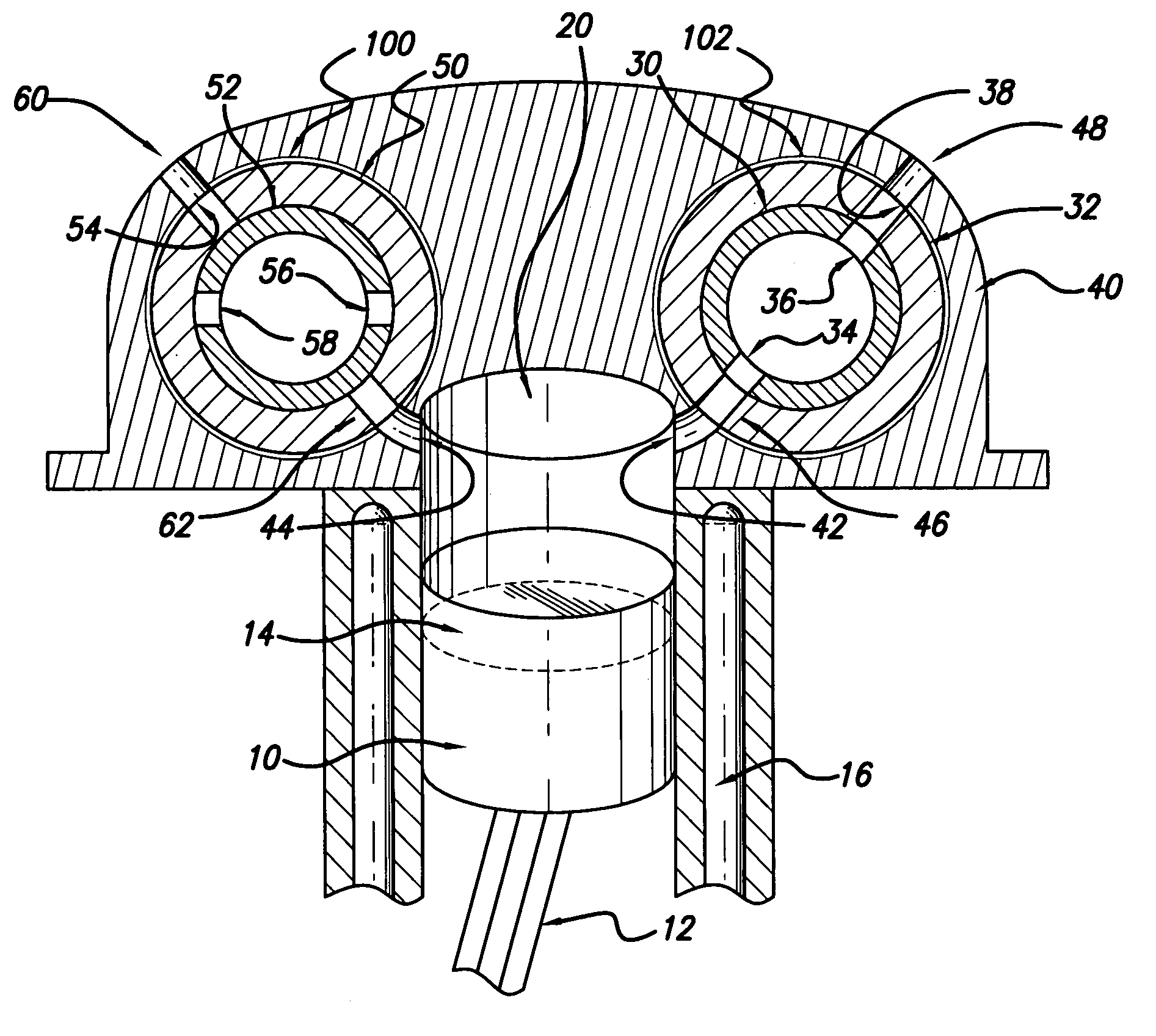
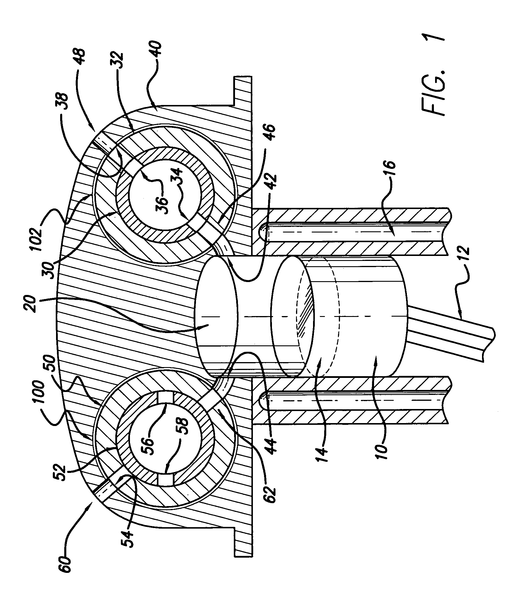
[0029]FIG. 1 depicts a cross-sectional view of an embodiment of the present invention. In one embodiment, rotary assembly valve (head unit cradle) 40 comprises of two sets of rotary valves. FIG. 1 illustrates an example configuration where the right side of the piston is the intake side and the left side is the exhaust side. It will be apparent to those skilled in the arts that in other embodiments the configuration can be reversed. In this example configuration, on the right hand side, inner slotted cylindrical tube 30 is located co-axially with outer slotted cylindrical tube 32. In one embodiment, inner slotted cylindrical tube 30 comprises of slots or apertures 34 and 36. Inner slotted cylindrical tube 30 rotates co-axially, relative to outer slotted cylindrical tube 32. In another embodiment, outer slotted cylindrical tube 32 and inner slotted cylindrical tube 30 both rotate, but in opposite direction. At a certain time during the rotation, apertures 34 and 36 of inner slotted c...


PUM


Abstract

This invention is a slotted cylindrical rotary valve assembly for an internal combustion engine, comprising of two sets of gear driven slotted cylindrical tubes in a cradle apparatus. Each set has two tubes located co-axially and rotates co-axially, and each tube is slotted to allow for improved transport of a fuel/air mixture and exhaust. In one embodiment, an intake set of tubes transport fuel/air through apertures on the tubes. The exhaust set of tubes transport exhaust through apertures (slots) on the tubes. The rotation of the tubes brings the apertures in timely alignment to allow fuel/air injection and exhaust in synchronization with the cyclical operation of the pistons in the combustion chambers. Effective sealing in one embodiment is achieved by using a modified piston with an extension wall extending longitudinally from the top of the piston to seal intake and exhaust orifices at the top of the chamber.

Description

[0001]This patent application claims priority to U.S. Provisional Patent Application No. 60 / 712,844, filed Sep. 1, 2005.BACKGROUND OF THE INVENTION[0002]1. Field of the Invention[0003]This invention relates to an internal combustion engine, and more specifically, to an improved apparatus and method of transporting combustible material transport to, and removing of exhaust from, the cylinder chamber of combustion.[0004]2. Discussion of Related Arts[0005]The operation of the internal combustion engine is organic and complex. The primary combustion occurs in the cylinder / chamber apparatus of the internal combustion engine. This combustion process can be likened to a cyclical process. The cycle first begins with an intake action, with a piston moving down a combustion chamber (cylinder apparatus) and drawing in a fuel / air mixture. Then, the piston compresses the fuel / air mixture as it travels in the combustion chamber that is temporarily sealed. Moreover, the compressed combustible fuel...

Claims


Application Information

Patent Timeline
IPC IPC(8): F01L7/00
CPCF01L7/026F01L7/027F01L2001/0537
Inventor MURRAY, MICHAEL J.
Owner MURRAY MICHAEL J
Why Eureka
Try Eureka