
Method and mold to control optical device polymerization

a technology of optical devices and polymerization, which is applied in the direction of foundry moulding apparatus, instruments, foundry patterns, etc., can solve the problems of uniform curing rate of ultraviolet polymerizable materials including resins, scattering of light rays, and non-uniform distribution of light intensity over lens-forming materials, so as to reduce the amount of energy available, remove any residual stress, and reduce the effect of unwanted stress

Inactive Publication Date: 2006-12-05
BARCLAYS BANK PLC AS SUCCESSOR AGENT
View PDF23 Cites 4 Cited by
  • Summary
  • Abstract
  • Description
  • Claims
  • Application Information

AI Technical Summary

Benefits of technology

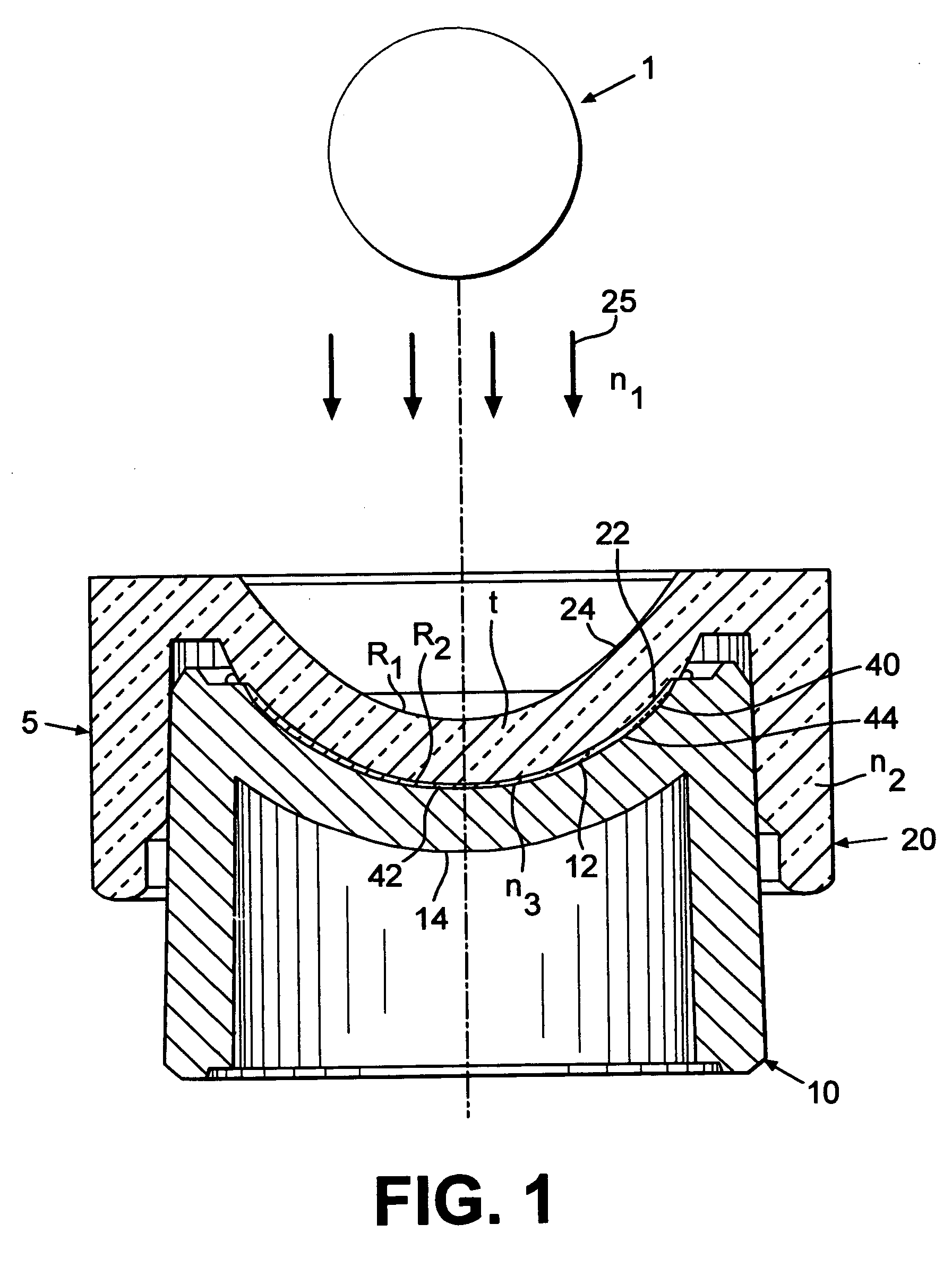
[0019]The present invention is a method for photocuring cast articles such as ophthalmic lenses in which defects in the cured article are reduced. By altering the pathway by which radiation rays reach the article to be cured, defects can be reduced. By controlling the relative intensity of radiation upon a particular portion of lens-forming material, the rate of polymerization taking place at various portions of the lens can be controlled. While this method works well with crystalline materials, it is particularly suited for use with mold materials which are amorphous.
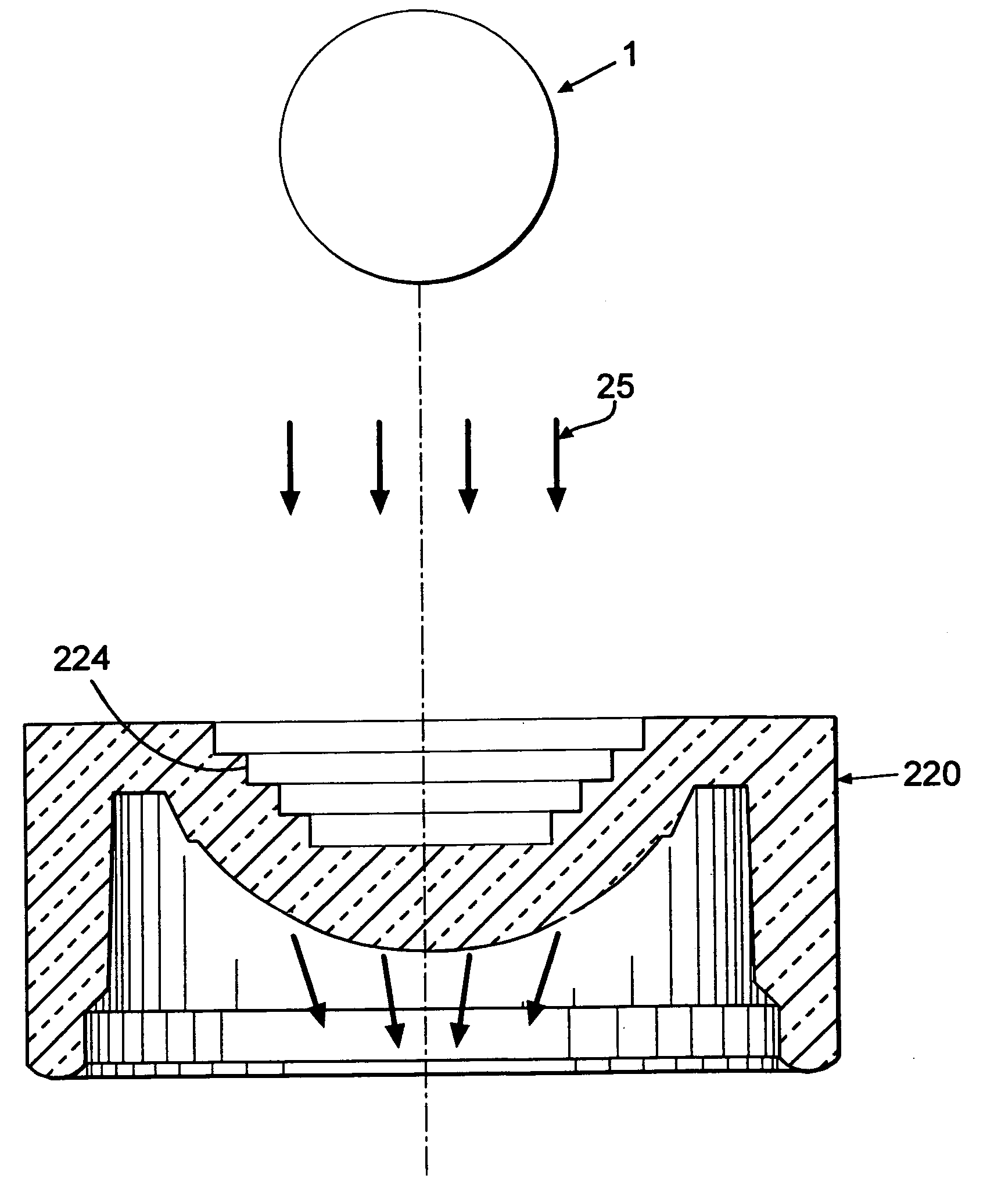
[0022]Alternately, a fresnel or diffractive lens may be placed between the light source and the mold. The lens may be placed at a predetermined distance away from the mold. The lens will alter the path of radiation, preferably ultraviolet (UV) radiation, passing through the mold and increase the energy available to the cured article. As a result, the distribution of radiation or energy across the mold will have a desired profile, which may remove any residual stress induced during curing. The result is a cured article such as a contact lens having an acceptable apex in the central portion of the lens. The optical element allows control of the illumination intensity profile reaching various sections of the contact lens. Unwanted stress induced by uncontrolled intensity profiles can be corrected. In addition, stress can be introduced in specific amounts and locations throughout the cast article as desired.
[0023]The ophthalmic lenses formed from these methods are relatively free from defects such as dimpling and warpage.

Problems solved by technology

For instance, some materials, such as thermoplastic crystalline polymers, may diffuse the radiation, causing a scattering of the light rays.
This may result in non-uniform distribution of light intensity over the lens-forming material.
This may lead to non-uniform curing rates of ultraviolet polymerizable materials including resins and monomers.
This stress may deteriorate the precision of the optical device face.
As a result, the slower curable portion (which receives lower radiation intensity) may show defects such as shrinkage.
In particular, in the case of contact lenses and spectacle lenses, this can produce lenses with unacceptable optical aberrations caused by uneven curing and stress.
“Dimpling” or warpage of the contact lens is a common problem caused by uneven curing.
Warpage is generally seen as the inability of the edge of a lens to have continuous contact with the molding surface upon which it contacts.
Other drawbacks seen with plastic spectacle lenses include “striations”, which are caused by uneven curing and stress.
Lipscomb et al. found that if incident UV light is not uniform throughout the lens, visible distortion pattern may appear in the finished lens.
Without the filter, the reflection of the metal mold and the glass lens result in non-uniform distribution of UV light and non-uniform curing speed.
The center of the resin cures faster than the outer perimeter, causing defects such as shrinkage in the resin.
None of the above art completely solves the problems which occur when using a mold assembly in which one mold portion or both molds is made from an amorphous material and acts as an optical device.
The resultant lens made from this particular mold assembly may have defects such as dimpling and warpage.

Method used


Image

  • Method and mold to control optical device polymerization
  • Method and mold to control optical device polymerization
  • Method and mold to control optical device polymerization

Examples


example 1

[0045]A series of HEMA lenses were cast according to conventional methods with the posterior mold portions prepared from an amorphous resin. Two sets of posterior mold portions had fresnel geometry cut into the non-critical surface with resulting hydrated lens powers of −6 D and −2 D. Two sets of posterior mold portions (also yielding hydrated lens powers of −2 D and −6 D) had controlled geometry (no junctions) and served as controls. After casting, the lenses were hydrated and parameters were measured.

[0046]

TABLE 1Posterior MoldSAG (mm)-2D Control3.581-2D Fresnel3.581-6D Control3.382-6D Fresnel3.420

[0047]The −6 D lenses made with the control molds failed to meet sag requirements because of dimpling / warpage. The −6 D lenses made with the Fresnel molds met the sag specification and did not have dimples. Other lens parameter requirements, although not listed, were also met by the −6 D lenses made with the Fresnel molds.


PUM

PropertyMeasurementUnit
Distanceaaaaaaaaaa

Abstract

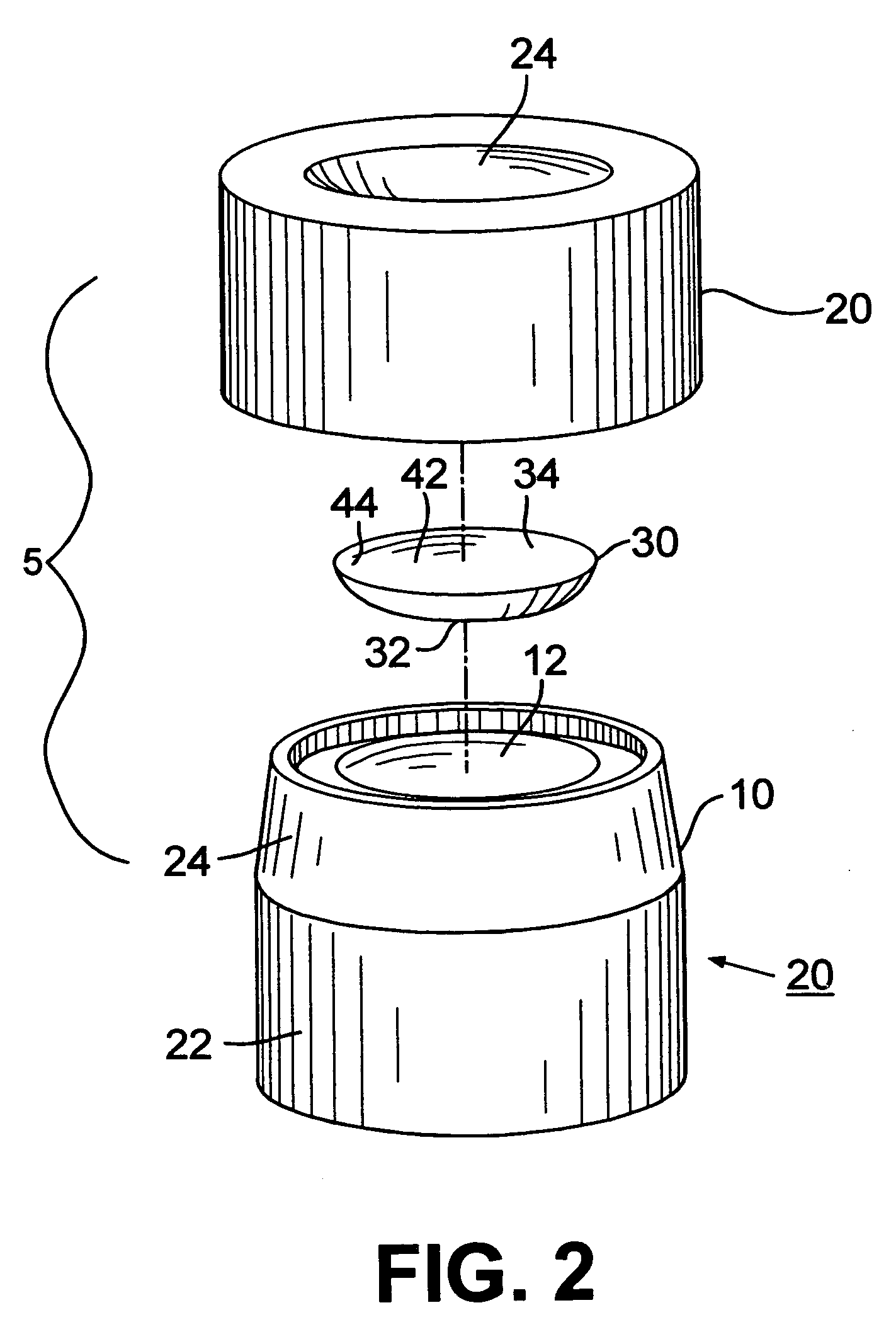
A method and mold assembly to control the polymerization of a cast optical device. The mold assembly includes at least one mold portion having a non-critical surface with fresnel or diffractive geometry. Alternately, a fresnel lens or diffractive lens may be placed at a predetermined distance from the mold.

Description

CROSS-REFERENCE TO RELATED APPLICATIONS[0001]This application claims priority of U.S. Provisional Ser. No. 60 / 193,906 which was filed Mar. 31, 2000, and is a continuation of U.S. Ser. No. 09 / 797,328 filed Mar. 1, 2001, now U.S. Pat. No. 6,772,988.BACKGROUND OF THE INVENTION[0002]The present invention is directed toward controlled curing of devices requiring optical cure. More specifically, the present invention provides a method for curing optical devices such that the devices undergo a more uniform polymerization, resulting in a reduction in defects such as dimpling and warpage in the cured device. In particular, the optical devices include ophthalmic lenses including contact lenses, intraocular lenses, spectacle lenses, corneal onlays and corneal inlays. More particularly, this method provides for a method to produce contact lenses having a controlled cure profile.[0003]It is often desirable to direct-mold optical devices such as contact lenses and intraocular lenses, rather than ...

Claims


Application Information

Patent Timeline
IPC IPC(8): B29D11/00B29C33/40B29C35/08B29D11/02
CPCB29C33/40B29C35/0888B29D11/00125B29D11/00269B29D11/00442B29D11/023B29C2035/0827B29K2025/00B29K2027/06B29K2105/0002B29K2995/0039B29K2995/0041B29L2011/0016B29L2011/0041B29L2011/005B29L2031/757Y10S425/808
Inventor ALTMANN, GRIFFITH E.
Owner BARCLAYS BANK PLC AS SUCCESSOR AGENT
Learn More