Magnetic sensor having a closed magnetic path formed by soft magnetic films

a magnetic sensor and closed magnetic path technology, applied in the field of high sensitivity magnetic sensors, to achieve the effect of high sn ratio of detection output and substantial double thickness of soft magnetic films

Inactive Publication Date: 2006-12-05
PANASONIC CORP
View PDF16 Cites 8 Cited by
  • Summary
  • Abstract
  • Description
  • Claims
  • Application Information

AI Technical Summary

Benefits of technology

[0011]According to the magnetic sensor of the other aspect, by forming the soft magnetic film into the strip-shape, in addition to the above-mentioned action and effect, when the external magnetic field is applied, demagnetization field produced in the soft magnetic film can be reduced. As a result, even in the case that a high frequency carrier signal of a relatively low frequency is used, the impedance value and the impedance change of the conductive nonmagnetic film are large, and a magnetic sensor having a high detection sensitivity is obtained.
[0013]According to the magnetic sensor of the further aspect, in addition to the above-mentioned actions and effects, the soft magnetic film, the conductive nonmagnetic film and the conductive film for giving the direct current bias magnetic field to the soft magnetic film are held by a nonmagnetic substrate. The magnetic sensor includes an effect which can detect the external magnetic field with a high sensitivity by causing a direct current to flow through the conductive film for applying a direct current bias magnetic field.
[0015]According to the magnetic sensor of the above-mentioned further aspect, in addition to the above-mentioned respective actions and effects, the following action and effect are included. Since the strip-shaped conductive nonmagnetic film is interposed between the first and the second soft magnetic films, an overall thickness of the soft magnetic film substantially doubles. Consequently, although demagnetization field increases when an external magnetic field is applied to the magnetic sensor, the absolute value of the impedance of the conductive nonmagnetic film doubles. Since a detection output level of the detection circuit is proportional to the value of the impedance, the level of the detection output becomes high and the SN ratio of the detection output becomes high.

Problems solved by technology

However, in the use for the magnetic sensor, there is a case requiring use of a carrier signal of a relatively low frequency.

Method used


Image

  • Magnetic sensor having a closed magnetic path formed by soft magnetic films
  • Magnetic sensor having a closed magnetic path formed by soft magnetic films
  • Magnetic sensor having a closed magnetic path formed by soft magnetic films

Examples


first embodiment

[0074]Description is made as to a magnetic sensor 9 of a first embodiment in the present invention with reference to FIG. 1 to FIG. 7.

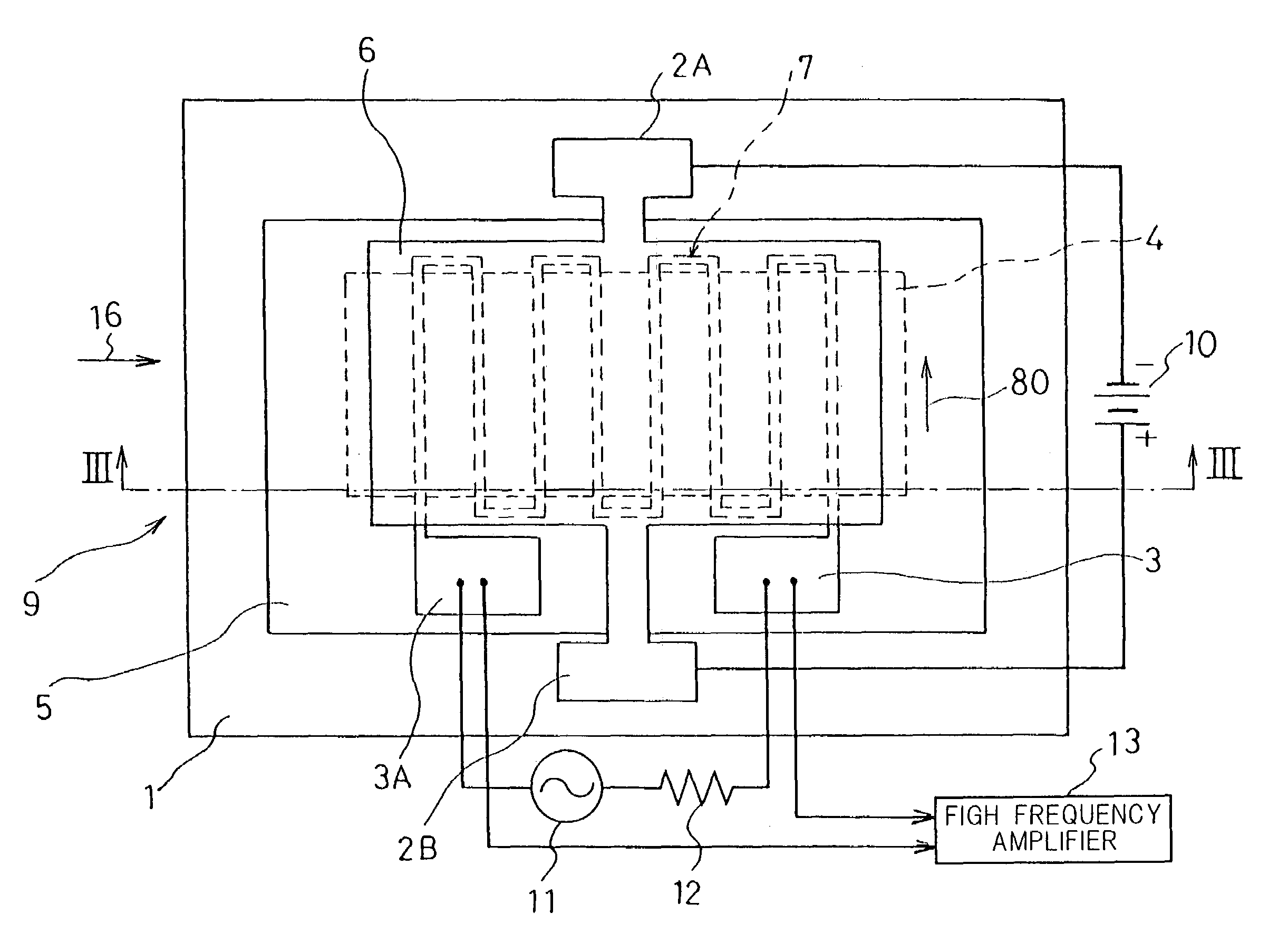
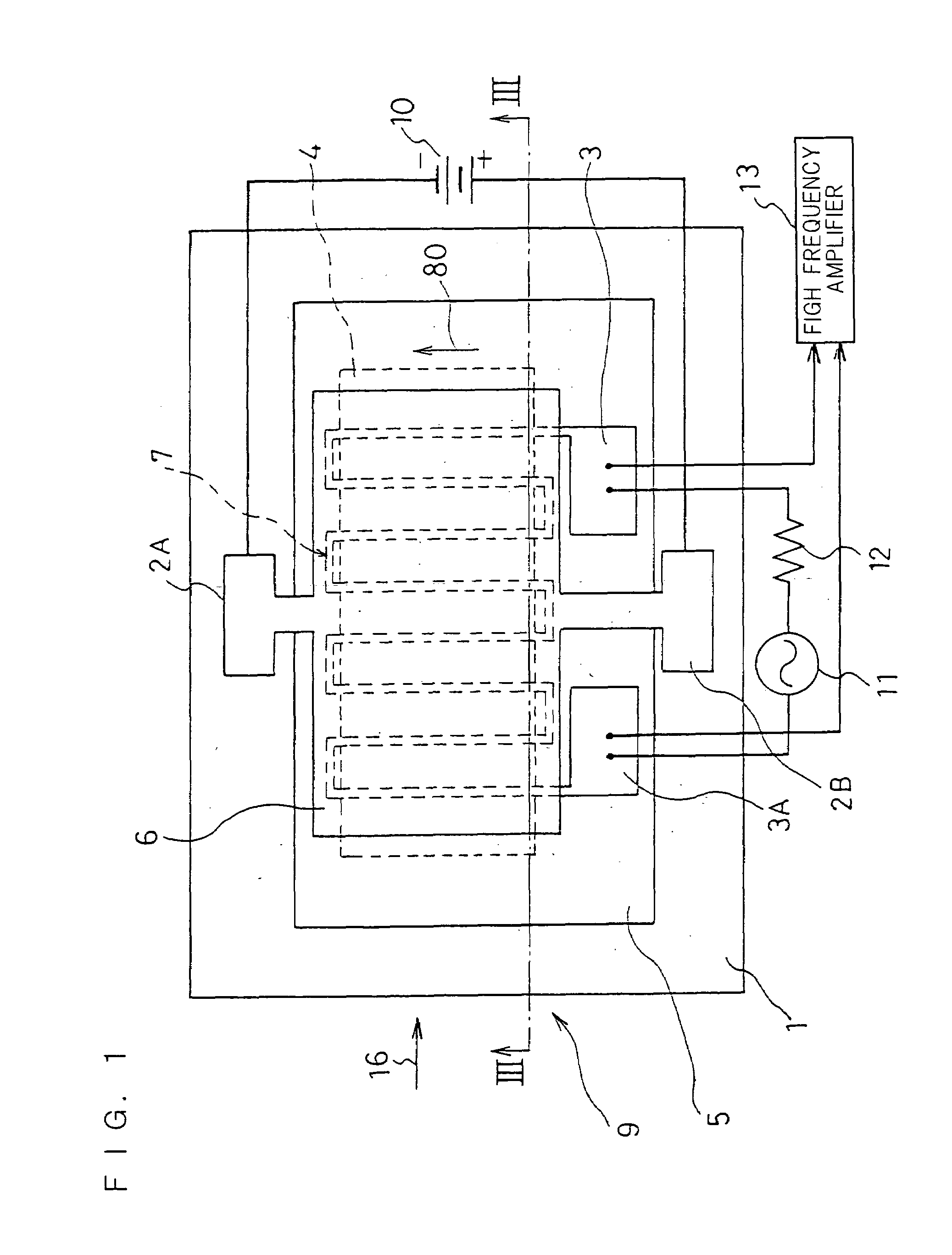
[0075]FIG. 1 is a plane view of the magnetic sensor 9 of the first embodiment in the present invention. FIG. 2 shows a plane view in a situation in which a conductive film 6 of copper (Cu) for applying a direct current bias magnetic field in FIG. 1 is removed in order to facilitate the understanding of inside structure. In order to avoid complication of the figures and to facilitate understanding, in all plane views including FIG. 1 and FIG. 2, depressions and projections existing on the surfaces are omitted from illustration. Part (a) of FIG. 3 is a cross-sectional view taken along the line III—III in FIG. 1, and part (b) of FIG. 3 is an enlarged fragmentary cross-sectional view of part (a) of FIG. 3. In cross-sectional views, in order to avoid complication of figures, cross-sections are not hatched.

[0076]In FIG. 1, FIG. 2, part (a) of FIG. 3 and par...

second embodiment

[0083]A magnetic sensor of the second embodiment in the present invention is described with reference to FIG. 8 to FIG. 12.

[0084]In the case that the frequency of the high frequency carrier signal applied to the magnetic sensor utilizing the magnetoimpedance effect is relatively low, in which carrier frequency is from 10 MHz to 20 MHz, the impedance of the conductive nonmagnetic film 7 of the above-mentioned magnetic sensor 9 in FIG. 1 is given principally by the product of the above-mentioned frequency and inductance of the conductive nonmagnetic film 7. Accordingly, in the present embodiment, the demagnetization field of the soft magnetic film 4 of the above-mentioned first embodiment is reduced, thereby to increase the inductance of the conductive nonmagnetic film 7, such that the impedance changes become large even with a weak magnetic field such as geomagnetism.

[0085]FIG. 8 is a plan view of a magnetic sensor of the second embodiment. Referring to the figure, a plurality of nar...

third embodiment

[0090]A magnetic sensor 9C of the third embodiment in the present invention is described with reference to FIG. 13 to FIG. 15.

[0091]FIG. 13 is a plan view of the magnetic sensor9C of the third embodiment in the present invention, and part (a) and part (b) of FIG. 14 are cross-sectional views taken along the line XIV—XIV in FIG. 13. In part (a) of FIG. 14 and part (b) of FIG. 14 of an enlarged fragmentary cross-sectional view, a film 18 including Cobalt (Co) and Platinum (Pt) (hereinafter is referred to as Co—Pt film) is formed on a nonmagnetic substrate 1 of Ni—Ti—Mg. The film 18 is magnetized so as to form the N and S poles in the right and left directions of the figure. Consequently, the Co—Pt film 18 becomes a permanent magnet film 18. Strip-shaped soft magnetic films 44 similar to those of the above-mentioned second embodiment are formed in approximately the same region as the permanent magnet film 18 on the permanent magnet film 18. Subsequently, an insulation film 5 is formed ...


PUM

PropertyMeasurementUnit
thickaaaaaaaaaa
thickaaaaaaaaaa
thickaaaaaaaaaa

Abstract

In order to obtain a magneto-impedance type magnetic sensor having a soft magnetic film facing to a conductive nonmagnetic film, and available a large impedance change with a carrier signal at a relatively low frequency, the magnetic sensor comprises a meander type conductive nonmagnetic thin film of zigzag shape formed with at least one pair of electrode terminals at both ends and a soft magnetic film which is strip-shaped so as to face thereto at a plurality of regions and has an easy axis of magnetization in a width direction of the strip shape, a high frequency carrier signal is applied to the above-mentioned electrode terminals and further a direct current bias magnetic field is applied. By performing AM detection of an AM modulation signal output from the above-mentioned electrode terminals, an impedance change of the conductive nonmagnetic film which is changed by external magnetic field is detected as a change of the high frequency carrier signal, thereby the external magnetic field can be detected.

Description

CROSS-REFERENCE TO RELATED APPLICATION[0001]This application is a Section 371 of International Application No. PCT / JP02 / 07188, filed Jul. 15, 2002, the disclosure of which is incorporated herein by reference.TECHNICAL FIELD[0002]The present invention relates to a high sensitivity magnetic sensor for detecting an external magnetic field by impedance change of a conductor due to a magnetism.BACKGROUND ART[0003]As a magnetic sensor for detecting a magnetism or a magnetic field with a high sensitivity, a magneto-impedance element which utilizes magneto-impedance effect is known. In the magneto-impedance element, a constant current of a high frequency is passed through a conductor provided adjacent to the magnetic poles of a soft magnetic body. When the magneto-impedance element is placed in a magnetic field, the impedance of the conductor is changed by the magnetic field. A magnetism is detected on the basis of the change of a high frequency voltage due to this change of the impedance o...

Claims


Application Information

Patent Timeline
Patent Type & Authority Patents(United States)
IPC IPC(8): G01R33/02G11B5/33G11B5/335
CPCG01R33/02G11B5/332Y10T29/49002Y10T428/1171G11B5/335H10N50/10
Inventor KUROE, AKIOMURAMATSU, SAYURIMURATA, AKIOTAKAHASHI, KENTOSAKI, YOSHIHIRO
Owner PANASONIC CORP
Why Eureka
Try Eureka