
Steering of directional sound beams

a directional sound beam and beam technology, applied in the field of ultrasonics and nonlinear acoustics, can solve the problems of high harmonic distortion in the sound generated, the inability to generate infinite harmonics in the preprocessing approach, and other technical challenges in the use of ultrasonic technology, and achieve the effect of significantly contributing to the noise pollution of the environmen

Inactive Publication Date: 2006-12-05
NANYANG TECH UNIV
View PDF12 Cites 54 Cited by
  • Summary
  • Abstract
  • Description
  • Claims
  • Application Information

AI Technical Summary

Benefits of technology

[0011]The present invention may address this problem by creating a private listening space for passers-by, passengers, shoppers and visitors without contributing significantly to noise pollution of the environment. At the same instant, a more coherent and intelligible message may reach the listener without experiencing too much distortion and noise interference. A variation of the present invention may provide a directional audio directory which can act as a guide for directing passers-by to their destinations. The present invention may allow conventional billboards each incorporating a sound beam to be placed relatively close to one another and still be able to maintain their respective private listening spaces without mutual interference.
[0015]The present invention may create a private listening space around the listener without disturbing his neighbors. The system of the present invention may accept an audio signal from any one of a plurality of sources including a CD player, FM radio receiver or digital broadcast radio receiver and transmit it within the area of the private listening space.
[0017]The present invention may provide a beamforming technique which may suitably adjust not only the phases of the primary waves, notably both the modulating signal in the audible range and the carrier signal in the ultrasonic range as discussed previously, but may also adjust the amplitudes or weights of the transducer elements in the parametric array to steer the sound beam. Such weight adjustments can be used to minimize spreading of the sound beam over large distances by the use of a Bessel distribution source. The latter may be constructed by weighting the arrangement of transducers by a Bessel function to produce a non-diffracting beam. The transducers may be driven with amplitudes which are adjusted to produce a zeroth order Bessel function. In theory such a beam travels to infinity without spreading. This may reduce the requirement of power and ensure high directivity along a desired path over a large distance. The transducers may be arranged in an annular or substantially annular array.

Problems solved by technology

This results in high levels of harmonic distortion in the sound generated.
However, due to the square root operation, this preprocessing approach generates an infinite number of harmonics.
Therefore, the amount of distortion of the demodulated signal is directly related to the bandwidth of the device, and the method requires bandwidth-intensive ultrasonic paths and emitters to get optimal performance.
However, other technical challenges remain in the use of ultrasonic technology for delivering audio.
In particular, the delivery of adequate power at low frequencies is a problem.
A problem with simultaneous audio-broadcasting of advertising material is that it creates noise pollution in public places such as shopping malls, public transport stations (bus stops and train terminals), conference and exhibition halls and the like.
This may create a relatively high level of interference and confusion for the listener who hears mixed signals from different broadcasting sources.

Method used


Image

  • Steering of directional sound beams
  • Steering of directional sound beams
  • Steering of directional sound beams

Examples


Embodiment Construction

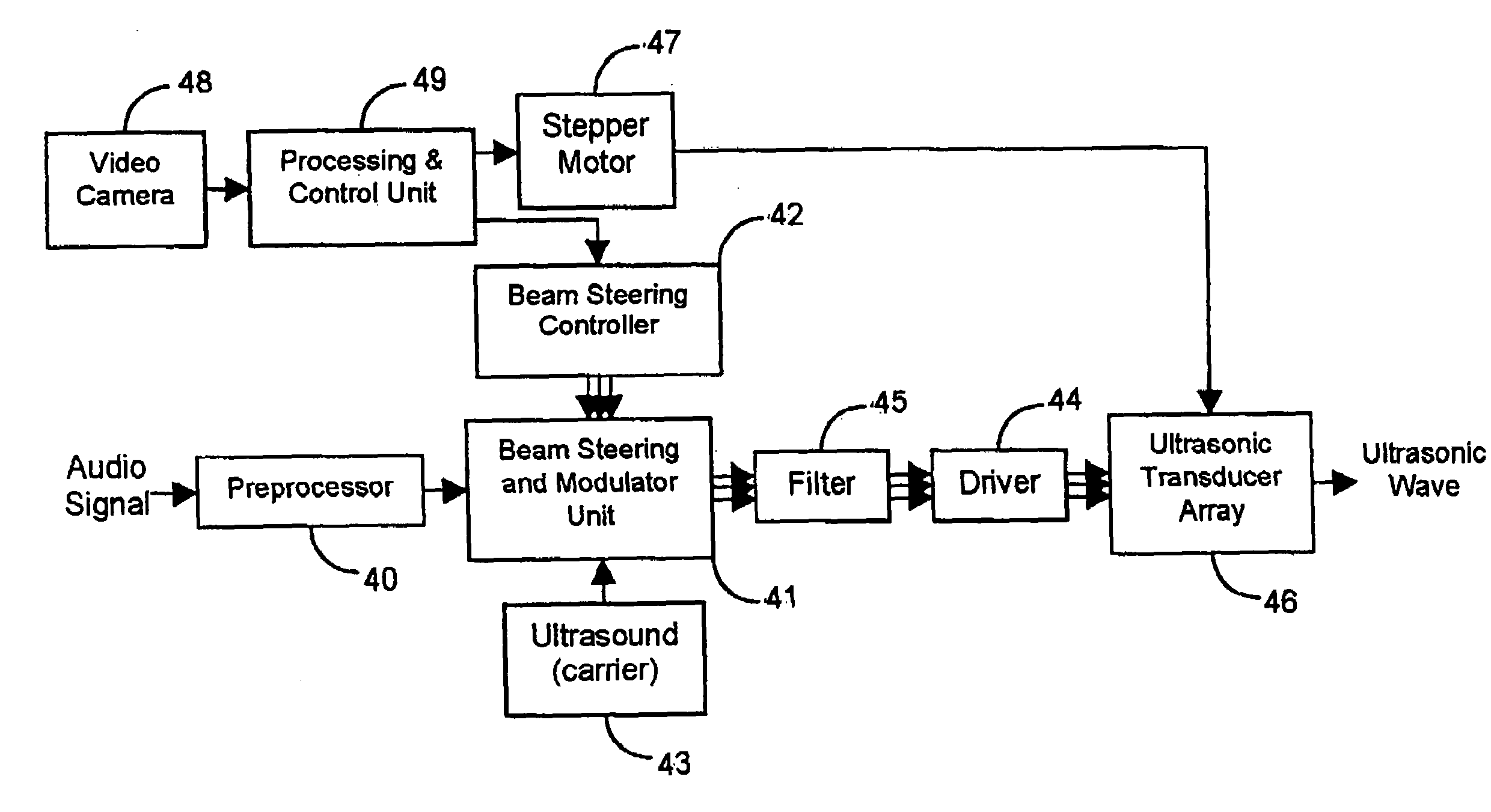
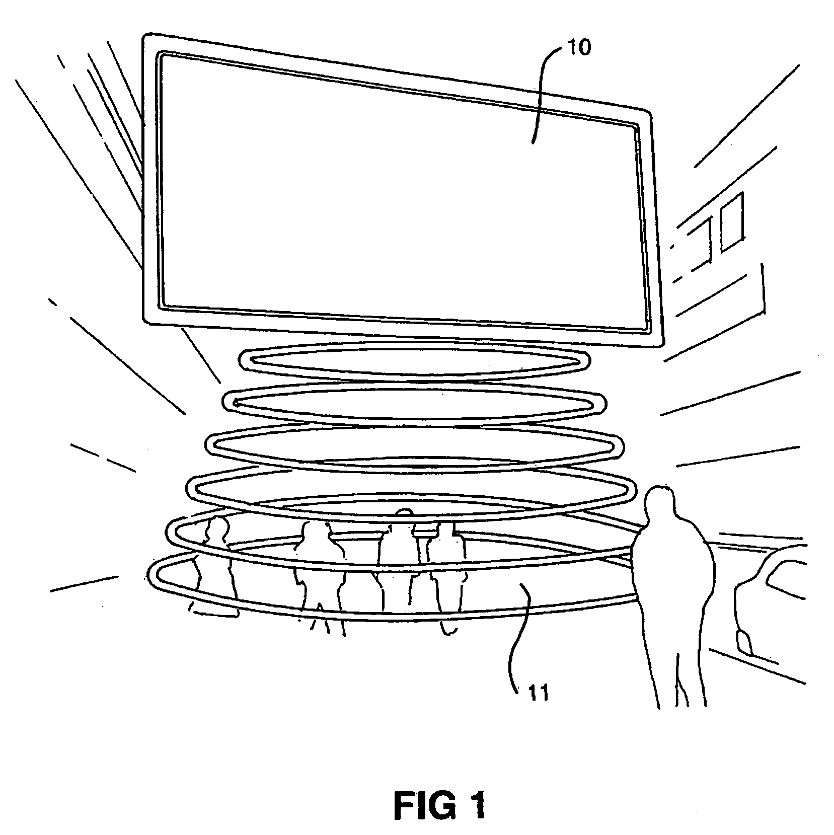
[0132]FIG. 1 shows billboard panel 10 which incorporates a system for generating a hyper-directional audible sound beam 11 according to the present invention. The billboard encompasses an implementation and integration of an array of ultrasonic transducers which generates the directional sound beam in association with a conventional billboard panel. The system may include a digital signal processing module that processes an audio signal from a sound source and sends it to a modulating and amplifying circuit. This in turn drives a group of ultrasonic transducers in the array and transmits a modulated ultrasonic beam. At high sound pressure levels, self-demodulation occurs due to nonlinear interaction in air and causes secondary audible frequencies to appear within the beam. Such a phenomenon of creating new sounds or virtual sources along a selected projection path (such that they reinforce one another) enables a hyper-directional sound beam to be produced in the audible range. These...


PUM


Abstract

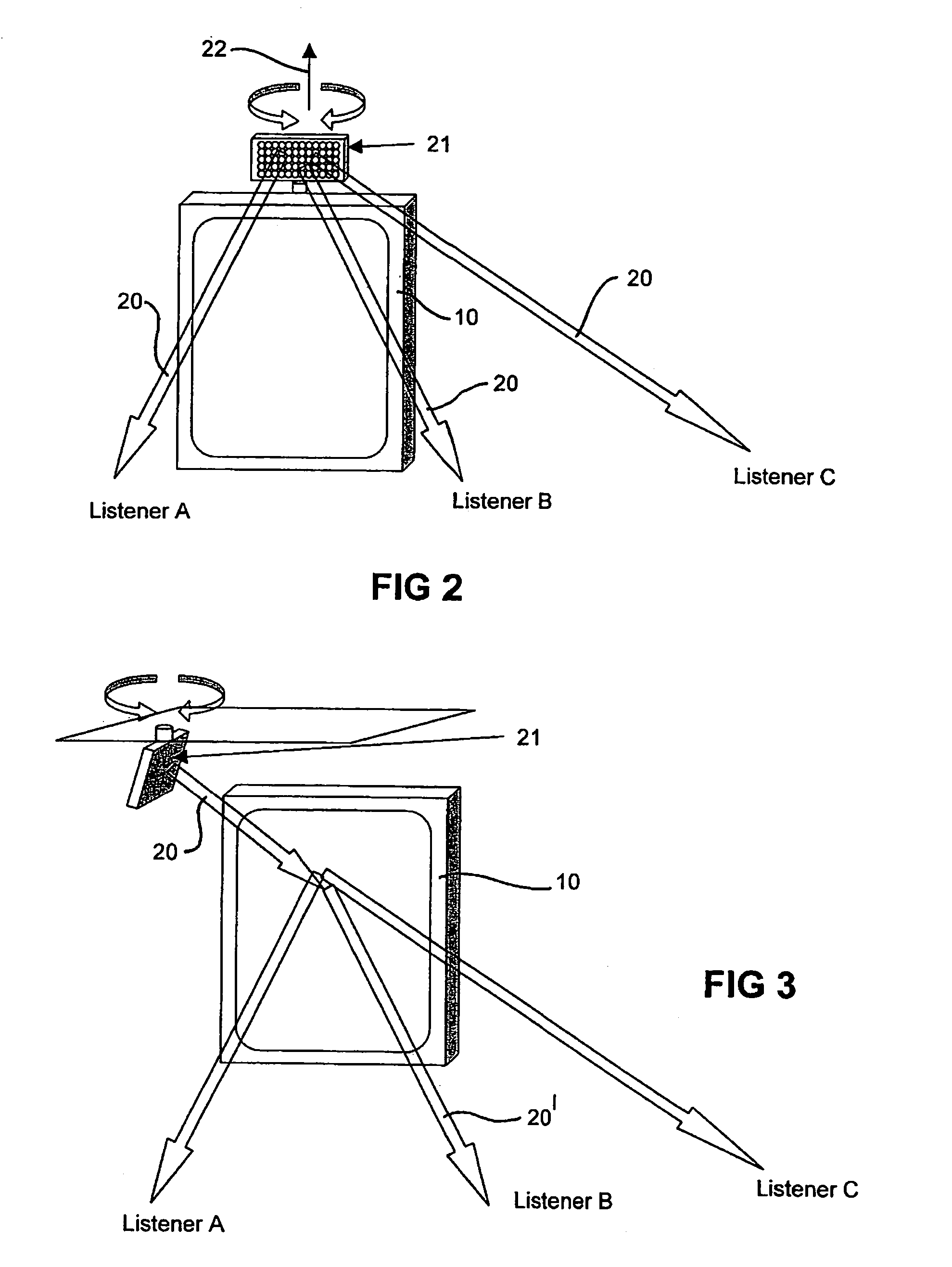
Apparatus is disclosed for steering a directional audio beam that is self-demodulated from an ultrasound carrier. The apparatus includes means for modulating a carrier signal with an audio signal and means for adjusting the amplitude and phase of at least one of the audio signal and / or the carrier signal to steer the audio beam to a desired direction. The apparatus also includes means for generating an ultrasound beam in the desired direction driven by the modulated carrier signal. The apparatus may include means for weighting the audio and / or carrier signal by a zeroth order Bessel function to synthesize a Bessel distribution source. A corresponding method for steering a directional audio beam is also disclosed. A harmonic generator may be used to generate harmonics of low frequencies in the audio signal. The harmonics may provide (upon demodulation) a psycho-acoustic impression of improved perception of low frequencies. Further, a modulated ultrasonic signal or an unmodulated audio signal may be band-passed into two or more different band-limited signals. The band-limited signals may be amplified and transmitted by ultrasonic transducers having mechanical resonance frequencies substantially equal to a characteristic frequency of the band-limited signals. Ultrasonic processing of the audio signal may include square root methods without generating large numbers of harmonics.

Description

RELATED APPLICATIONS[0001]This application is a continuation of and claims priority under 35 USC § 119, 120 and / or 365 to PCT patent application No. PCT / SG02 / 00195, filed Aug. 28, 2002, which claimed priority of Singapore Patent Application No. 200200437-2, filed Jan. 25, 2002, Singapore Patent Application No. 200105345-3 filed Aug. 31, 2001 and Singapore Patent Application No. 200105344-6, filed Aug. 31, 2001.FIELD OF THE INVENTION[0002]The present invention relates to the field of ultrasonics and nonlinear acoustics for generating hyper-directional audible sound beams. In particular the invention relates to a method and apparatus for steering the hyper-directional sound beams to a desired location and to systems incorporating such method and apparatus. The present invention also presents preprocessing methods for reducing distortion and enhancing perception of bass frequencies, as well as techniques for reducing bandwidth requirements in associated ultrasonic transducers.BACKGROUN...

Claims


Application Information

Patent Timeline
Patent Type & Authority Patents(United States)
IPC IPC(8): H04B3/00G01S15/00H04B1/02H04B5/00H04R3/00G10K11/26G10K15/02
CPCG10K11/26G10K15/02G01N2291/02491H04R2217/03
Inventor YANG, JUNGAN, WOON SENGER, MENG HWALEE, CHEE MUN KELVINTAN, KHIM SIALIEW, YEW HINKARNAPI, FURI ANDISHA, KANWANG, YI
Owner NANYANG TECH UNIV
Learn More