
Electrochemical sensor

Active Publication Date: 2006-12-12
MSA TECH
View PDF13 Cites 37 Cited by
  • Summary
  • Abstract
  • Description
  • Claims
  • Application Information

AI Technical Summary

Benefits of technology

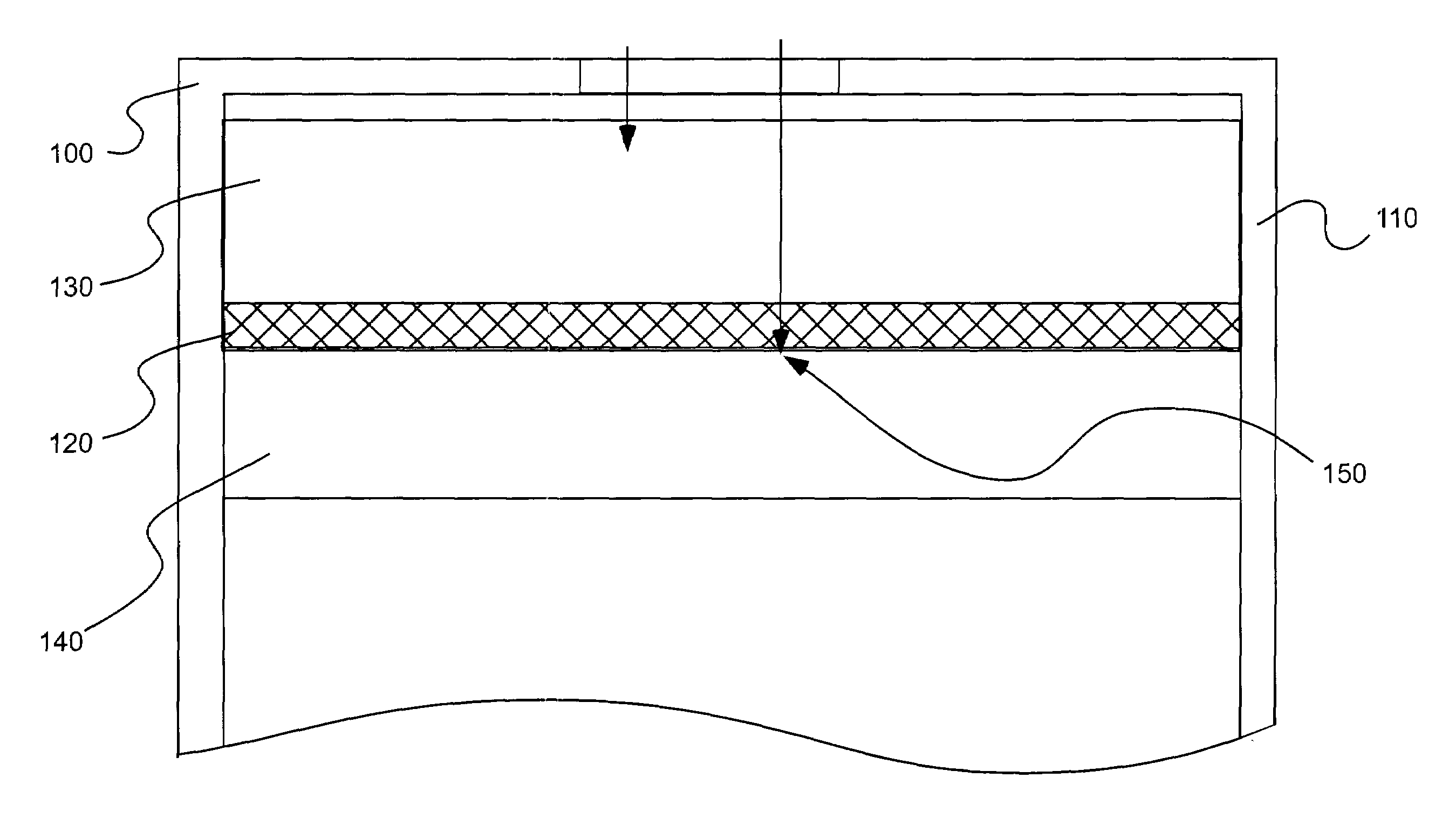
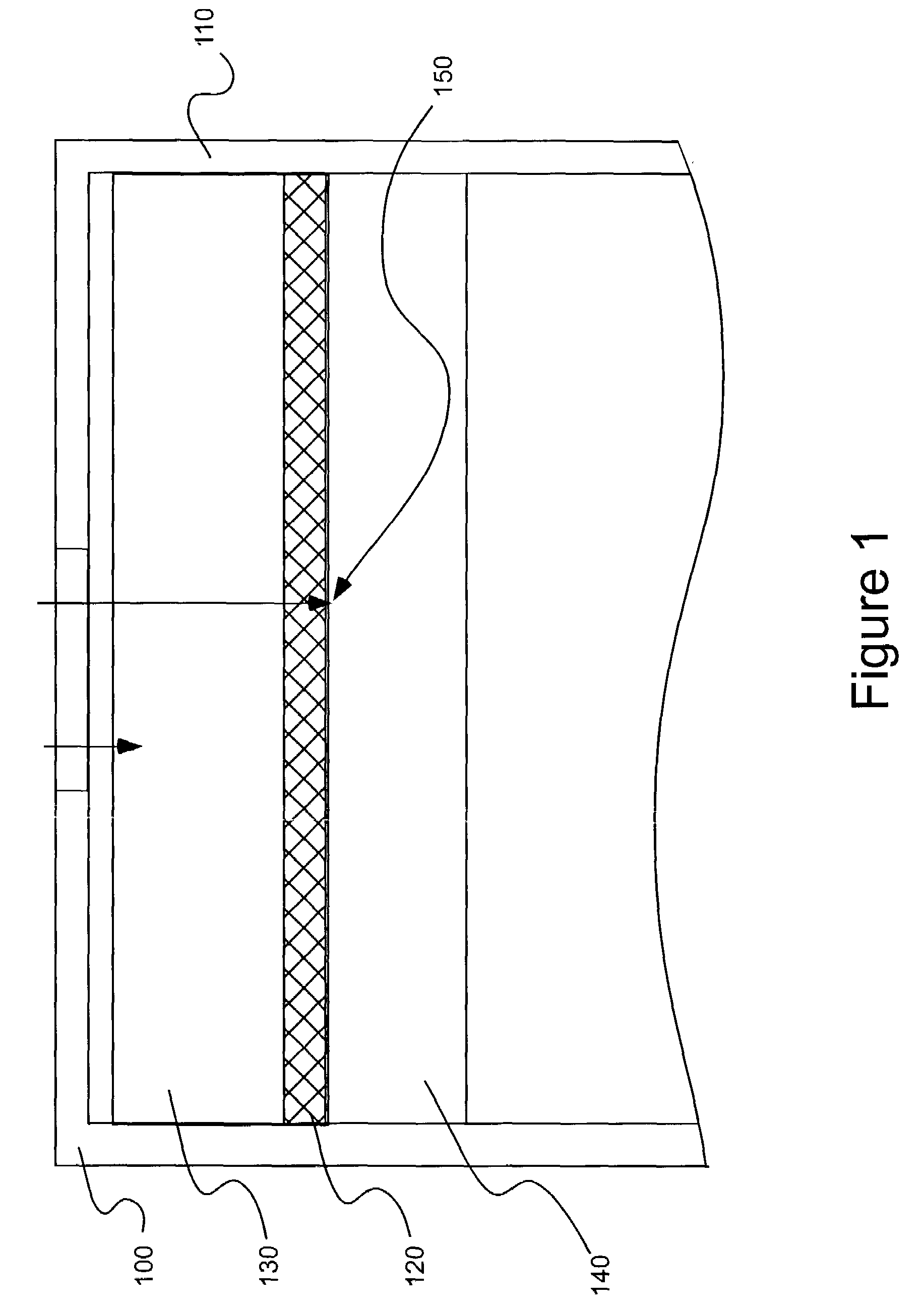
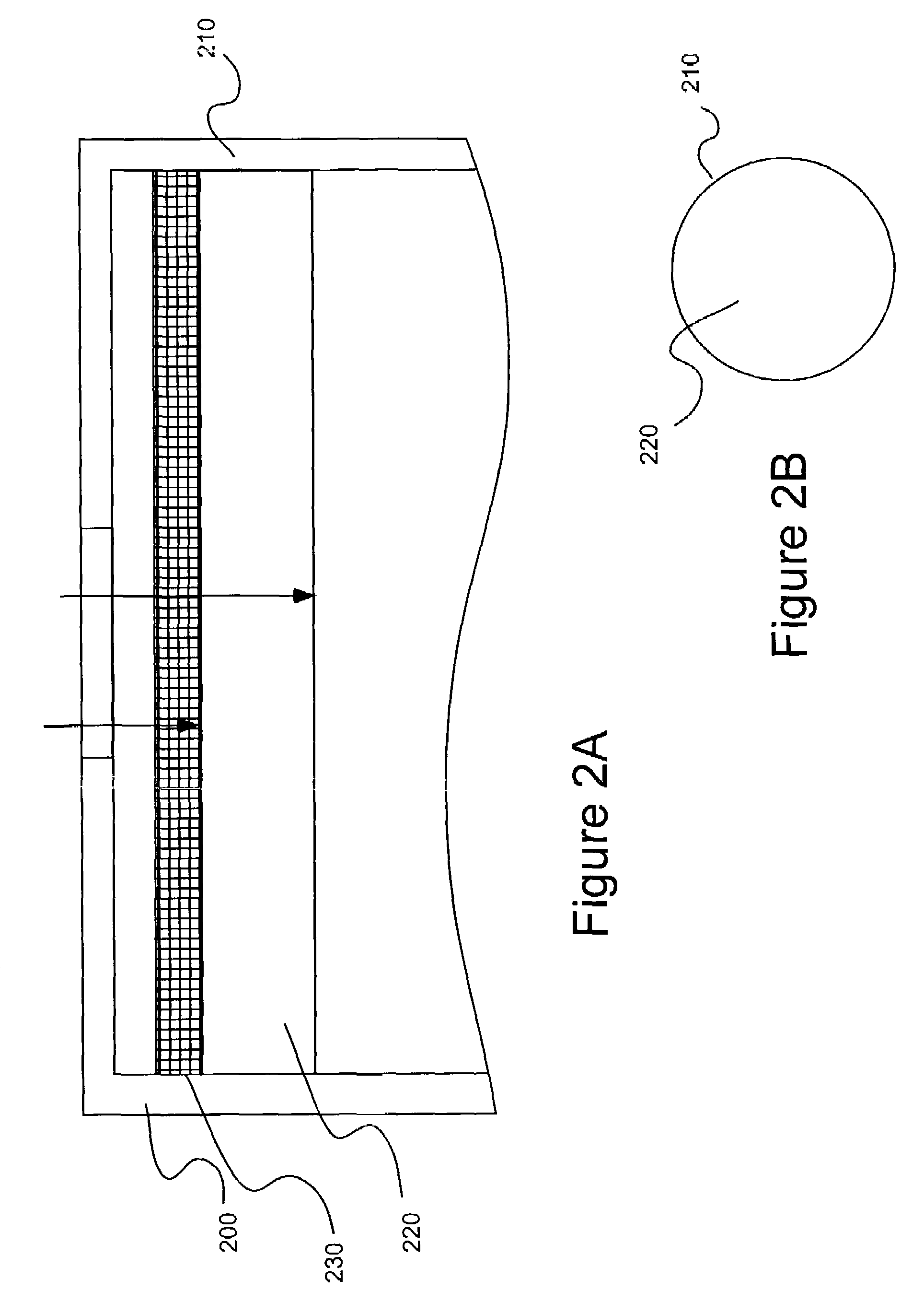
[0013]In current electrochemical sensors in which a liquid electrolyte is used, the liquid electrolyte can penetrate a solid catalyst layer formed on an electrode of the sensor to provide conductive contact. In a number of electrochemical sensors (for example, electrochemical sensors with metallic housings) it is desirable, however, to immobilize the electrolyte. In current sensors with immobilized electrolytes, there is generally no penetration of a catalyst layer of an electrode thereof by the immobilized electrolyte. Interfacial contact between the electrolyte and the catalyst can thus be diminished as compared to sensors in which a liquid electrolyte is used. The present inventors have discovered that good contact between a catalyst and an immobilized electrolyte can be achieved, while maintaining catalyst activity, by dispersing / immobilizing the catalyst within the electrolyte.
[0022]The electrodes, sensors and methods of the present invention improve catalyst electrolyte contact and improve sensor response time as compared to sensors incorporating electrodes in which a hydrophobic catalyst layer is deposited upon a porous membrane. Moreover, the electrodes of the present invention are relatively easy and inexpensive to manufacture in various sizes and, particularly, in reduced size as compared to currently available electrodes. The reduced size of the electrodes of the present invention facilitate the manufacture of compact sensors. Additionally, the electrodes of the present invention are easily formed as, for example, stacks of multiple electrodes or multiple-layer electrodes for manufacture of compact sensors suitable for detection of multiple analytes. The electrodes of the present invention are also suitable for use with generally any electrolyte, including aqueous, inorganic and / or organic electrolytes. The electrolytes used with the electrodes of the present invention can also be acidic, basic or neutral. Still further, the electrodes of the present invention have been found to provide improved response signals, particularly with catalyst materials of intrinsically low surface area (for example, gold).

Problems solved by technology

Such change can result in undesirable side reactions and / or nonlinear behavior over the range of analyte concentrations desired to be detected.

Method used


Image

  • Electrochemical sensor
  • Electrochemical sensor
  • Electrochemical sensor

Examples


experimental examples

[0049]A number of electrodes as illustrated in FIGS. 3A and 3B were tested for various analyte gases using various electrode catalysts in a two-electrode sensor configuration as summarized in Table 1. The catalysts used in the studies of the present invention are further characterized in Table 2.

[0050]

TABLE 1AnalyteActive CatalystActive CatalystBiasGasWorking ElectrodeCounter ElectrodePotentialH2SIridiumIridium0mVCOPlatinumPlatinum0mVNO2Activated CarbonActivated Carbon0mVSO2GoldPlatinum0mVNOCarbonPlatinum+300mVNH3IridiumIridium+235mV

[0051]

TABLE 2Surface Area,CatalystManufacturerm2 / gSensorIridiumEnglehard15.5–21.5H2SPlatinumEnglehard>25CO, SO2, NOActivated CarbonJohnson MattheyNot AvailableNO2 (75%)Carbon BlackCabot94NO2 (25%)(Regal 330R)GoldTechnic Inc.0.4–1.0SO2GraphiteSigri Great LakesNot AvailableNO(EG-31)Carbon Co.

Each of the sensors studied included a working and counter electrode as described above. In forming the bi-layer electrodes, the electrolyte was H2SO4, the high-surfac...


PUM


Abstract

An electrode for use in an electrochemical sensor includes a catalyst dispersed within an electrolyte. Preferably, the catalyst is immobilized within a matrix of the electrolyte. In one embodiment, the electrode of the present invention includes at least one catalyst / electrolyte layer having a mixture of a powdered catalyst, a powdered, quasi-solid electrolyte and a binder material compressed together. The quasi-solid electrolyte can include a liquid electrolyte immobilized by a high-surface-area, high-pore-volume solid.

Description

CROSS-REFERENCE TO RELATED APPLICATION[0001]This application claims benefit of U.S. Provisional Patent Application 60 / 311,909 filed Aug. 13, 2001, the contents of which is incorporated herein by reference.BACKGROUND OF THE INVENTION[0002]The present invention relates to an electrochemical sensor, and particularly, to an electrochemical sensor having improved response time.[0003]In a typical electrochemical gas sensor, the gas to be measured typically passes from the atmosphere into the sensor housing through a gas porous or gas permeable membrane to a working electrode (sometimes called a sensing electrode) where a chemical reaction occurs. A complementary chemical reaction occurs at a second electrode known as a counter electrode (or an auxiliary electrode). The electrochemical sensor produces an analytical signal via the generation of a current arising directly from the oxidation or reduction of the analyte gas (that is, the gas to be detected) at the working and counter electrode...

Claims


Application Information

Patent Timeline
IPC IPC(8): G01N27/403G01N27/28G01N27/404G01N27/416G01N27/49
CPCG01N27/4045
Inventor DAVIS, BRIAN K.SCHEFFLER, TOWNER B.BUSBY, JR., LOUIS J.NEIGHOFF, JR., JOHN F.
Owner MSA TECH
Learn More