Source for energetic electrons

a source and electron technology, applied in the field of energetic electron sources, can solve the problems of short mean time between failures of electron beam devices, limited power output, air poisoning or disease-causing toxins, etc., and achieve the effect of facilitating direct bonding of beam exit foils, facilitating good heat sinking of beam exit window materials, and simplifying beam optics

Active Publication Date: 2006-12-12
VALENCE CORP +1
View PDF33 Cites 27 Cited by
  • Summary
  • Abstract
  • Description
  • Claims
  • Application Information

AI Technical Summary

Benefits of technology

[0005]The use of a nominally cylindrical geometry for the device makes use of the inherent strength of a cylinder to support and hold the output foil and provides for simplified beam optics so that a higher percentage of the emitted and accelerated electrons strike and exit the beam exit window foils. Thus the output of the device is increased over prior art electron sources. The cylindrical shape also facilitates direct bonding of the beam exit foils to support plates in the vacuum housing. Such bonding facilitates good heat sinking of the beam exit window material that in turn allows the use of thicker foils than previously usable in standard equipment, thus reducing the probability of metallurgical failure of the foil material. This geometry permits a larger surface area to be used as exit areas so that equivalent or greater power can be emitted with reduced heat stress per unit area of exit window. The cylinder and cathode can be lengthened or the cylinder made larger in diameter, or both, to increase effective window area and / or voltage, thus increasing power output from the electron emitter.

Problems solved by technology

Toxics in this application means poisonous or disease causing toxins in air, other gasses, mists or attached to fine particles.
However, electron beam (e-beam) devices in use suffer from short mean time between failures, limited power output, or high costs for large power output.
Failure modes arise from failures of the source of emissions and failures of the foil due to pinholes caused by poor metallurgical integrity or through excessive heating by electrons passing through or a combination of both.

Method used


Image

  • Source for energetic electrons
  • Source for energetic electrons
  • Source for energetic electrons

Examples


Embodiment Construction

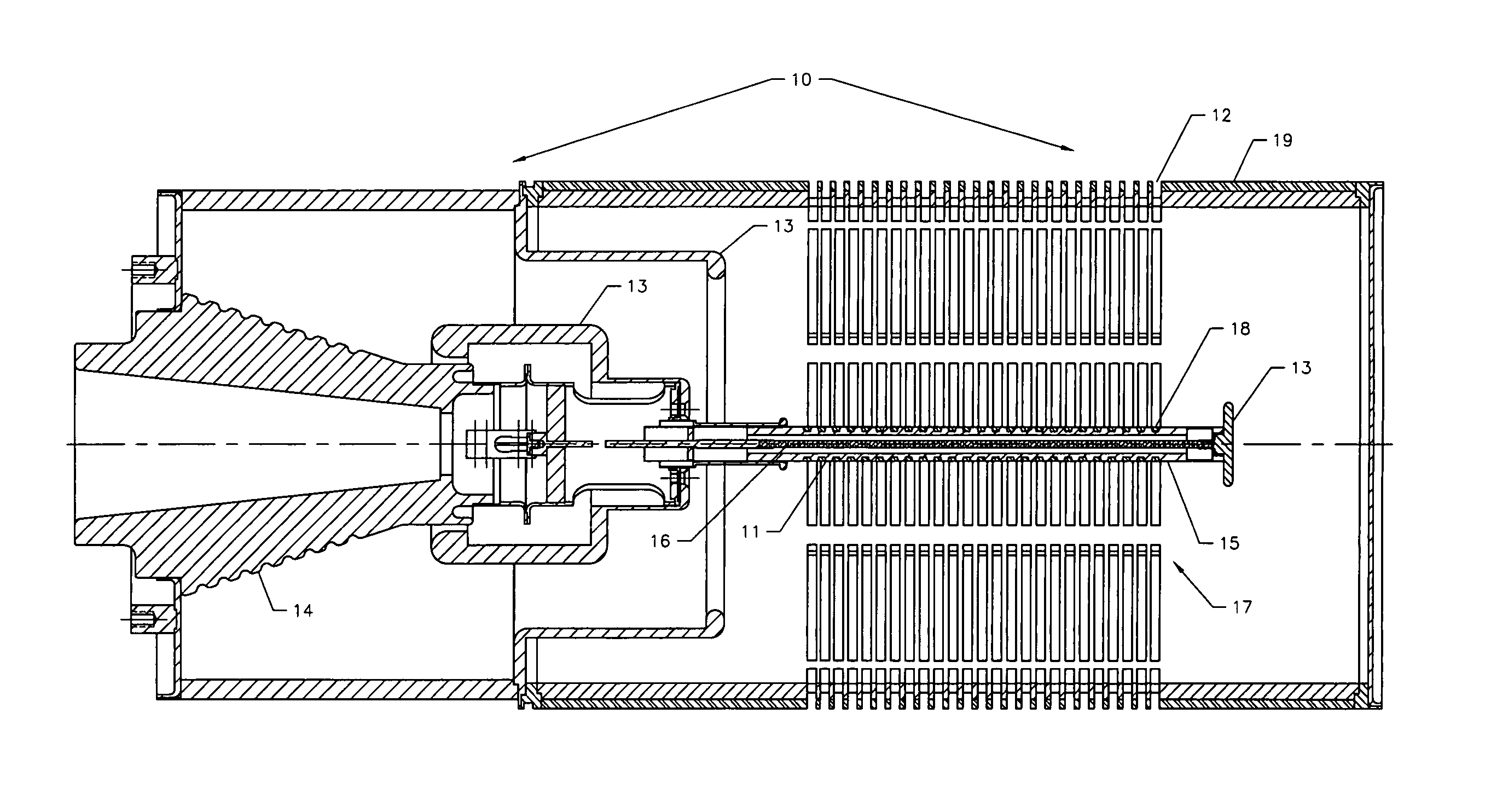
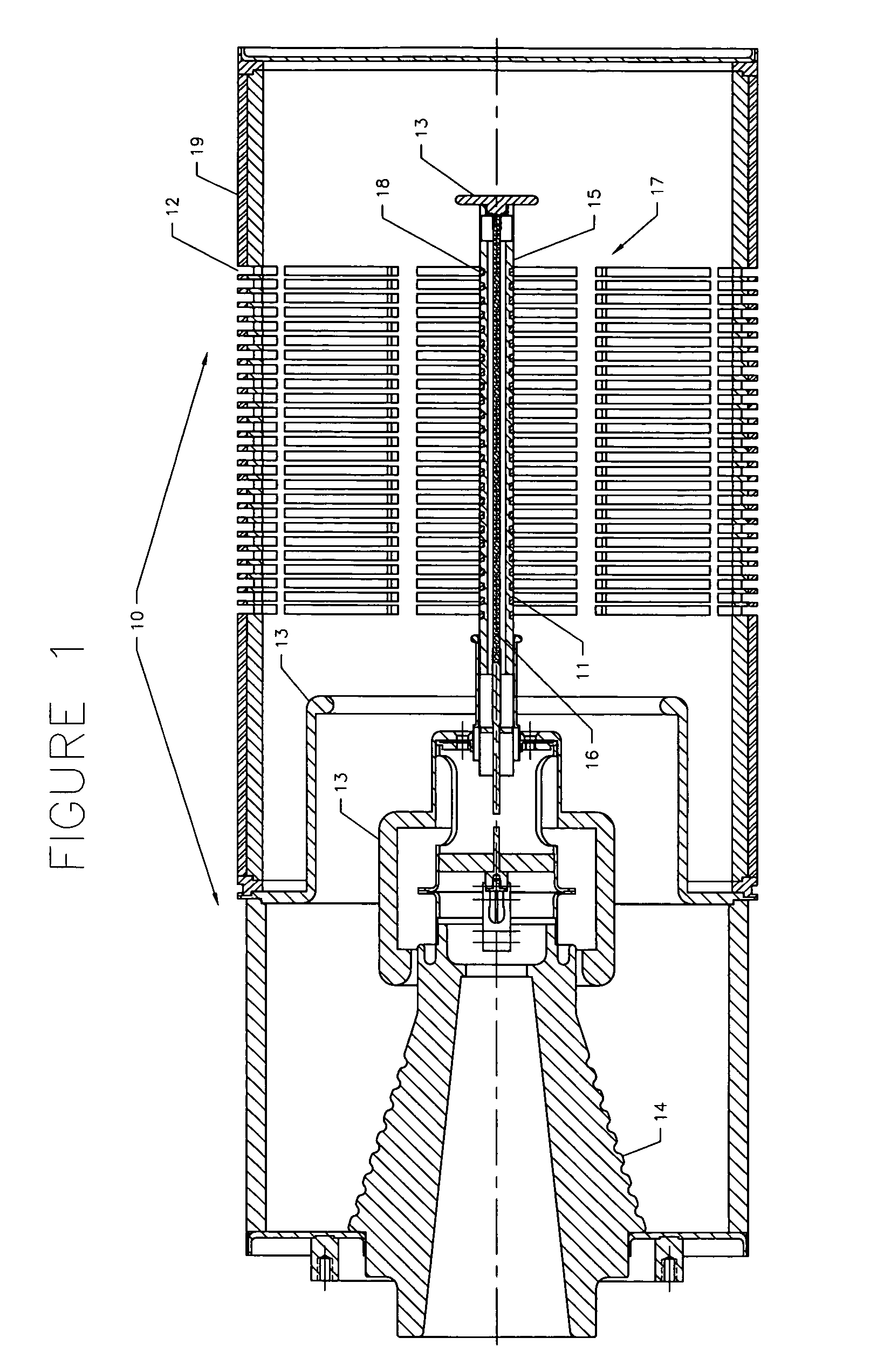
[0011]Referring now to FIG. 1, there is illustrated an embodiment of this invention. The electron flux generator 10 is of a generally cylindrical shape. It uses materials and construction techniques typically used in the design and manufacture of microwave tubes. For example a stainless steel shell for the tube will provide the structural strength needed to maintain the tube with a vacuum within and atmospheric conditions without. The electron flux generator 10 includes a cathode 11 which may comprise a dispenser type or an oxide type cathode, for example, or a tungsten wire filament, or filaments, heated to a high temperature or any variety of cold electron emission devices. Either a dispenser or oxide type cathode offers operation at relatively low temperature compared to a tungsten wire filament. The dispenser cathode, for example, operates at a temperature of less than about 1000° C. while an oxide type cathode operates at a temperature of less than about 850° C., compared to a ...


PUM


Abstract

There is described, for example, a generally cylindrical generator of energetic electrons that releases electrons from a vacuum enclosure into a surrounding space including into the atmosphere where the electrons may be used for a variety of applications including clean up of a flowing gas stream. Described is an efficient electron generator that emits more beam power than past structures in this class of devices and does so in connection with the treatment of gases or surfaces requiring treatment.

Description

[0001]This invention relates to an improved source or generator for the creation of energetic electrons. This device comprises a vacuum structure generally cylindrical in nature to facilitate the emission of electrons and to control their flow from a source within the vacuum into a surrounding volume where the electrons are put to use. The instant invention is more efficient than heretofore electron devices currently known for the same or similar applications, where efficiency is the ratio of beam power emitted into the region intended for its application compared to the input electrical power required to operate the electron beam device.BACKGROUND[0002]Various systems are dependent on applying energetic electrons in systems characterized by the absence of vacuum conditions. One such system uses electrons to reduce or eliminate volatile organic compounds contained in gas flows. This application is described, for example, in U.S. Pat. Nos. 5,319,211, 5,357,291 and 5,378,898. Electron...

Claims


Application Information

Patent Timeline
Patent Type & Authority Patents(United States)
IPC IPC(8): H01J37/06H01J33/00H01J33/04
CPCH01J33/00H01J33/04
Inventor DALLY, EDGAR B.GAGNE, DONALD R.ESPINOSA, ROBERT J.CHRISTESON, JOEL
Owner VALENCE CORP
Why Eureka
Try Eureka