Method and arrangement for treatment of fluid

a fluid treatment and fluid technology, applied in the field of downhole, to achieve the effect of reducing pressure loss, increasing pressure drop, and reducing pressure loss

Inactive Publication Date: 2006-12-26
AKER SUBSEA LTD
View PDF19 Cites 16 Cited by
  • Summary
  • Abstract
  • Description
  • Claims
  • Application Information

AI Technical Summary

Benefits of technology

[0019]Since the densities of the three phases are increasing in the following order: ρg, ρo and ρw, a removal of the water from the well fluid will reduce the density of the remaining phases and thereby reduce the pressure loss, i.e. the pressure gradient is steeper. Injection of gas into the water will reduce the density of the combined phases (gas-water) and thereby reduce the pressure loss. However, a limitation on the amount of gas feasible for injection is limited by the second term of equation (1). Since the dynamic pressure drop is increasing by Q2 the injection of gas above a certain amount will (at least in theory) increase the pressure drop. In other words: the use of gas for artificial lift will increase frictional pressure drop since the total volume flow increases with gas being brought back to the host. At long tie-back distances the net effect of using gas lift becomes low when gain in static pressure is reduced by increased dynamic pressure drop. However, downhole gas lift can be accomplished locally at the production area by separating and compressing a suitable rate of gas taken from the well fluid and distributing the gas to the subsea wells for injection. This recycling of gas reduces the amount of gas flowing in the pipeline, compared to supplying gas from the host. The advantage of this can be utilized by increasing the production rate from the wells, reducing pipeline size or increasing capacity by having additional wells producing via the pipeline. In addition to this, gas lift at the riserbase will become more effective with this configuration.

Problems solved by technology

However, it has not been suggested until now to use gas for artificial lift of the water.

Method used


Image

  • Method and arrangement for treatment of fluid
  • Method and arrangement for treatment of fluid
  • Method and arrangement for treatment of fluid

Examples


first embodiment

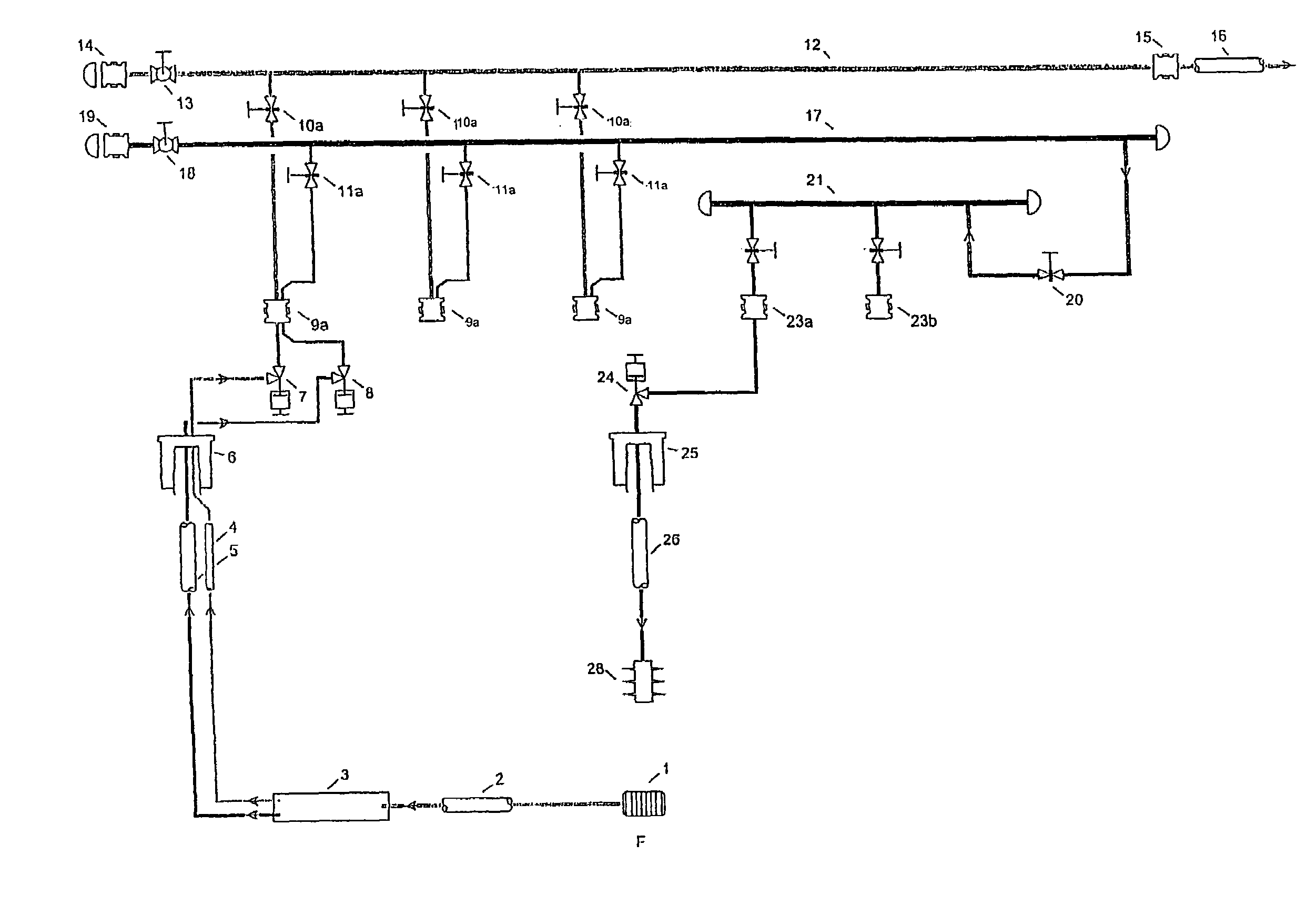
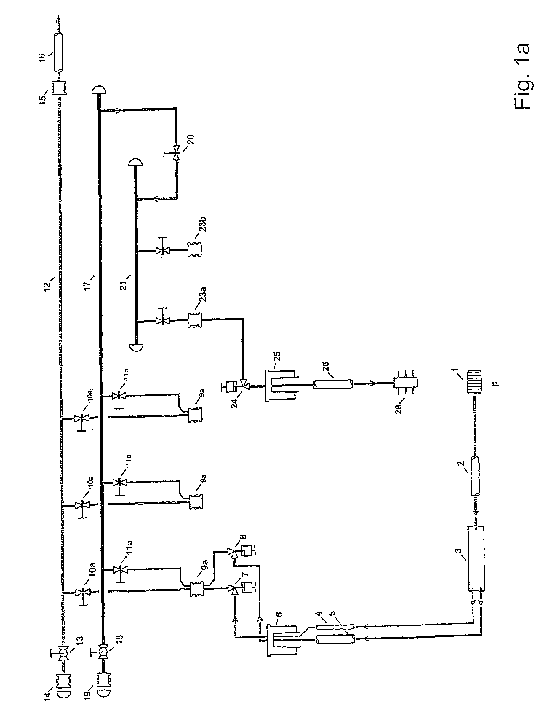
[0039]FIG. 1a illustrates a layout of a production manifold and well according to the present invention. The layout illustrates production of fluid from an underground formation F and transportation of the fluid to the subsea manifold.

[0040]Hydrocarbons (oil and in some cases gas) mixed with water is emanating from the reservoir F flows via sand screens 1 into the well, and is transported in a tubing 2 to a downhole separator 3 where the water phase and hydrocarbon phase are separated. The separator 3 may be of gravity or centrifugal type. The water phase and hydrocarbons phase of the well fluid are transported to the wellhead 6 in separate flow channels 4, 5. Typically the hydrocarbons will be routed to a production tubing 4 whilst the water is routed to the annulus 5 formed between the production casing and the production tubing. Alternatively, in a dual completion system both phases will be brought to the seabed in individual production tubes.

[0041]Using a dual function x-mas tre...

second embodiment

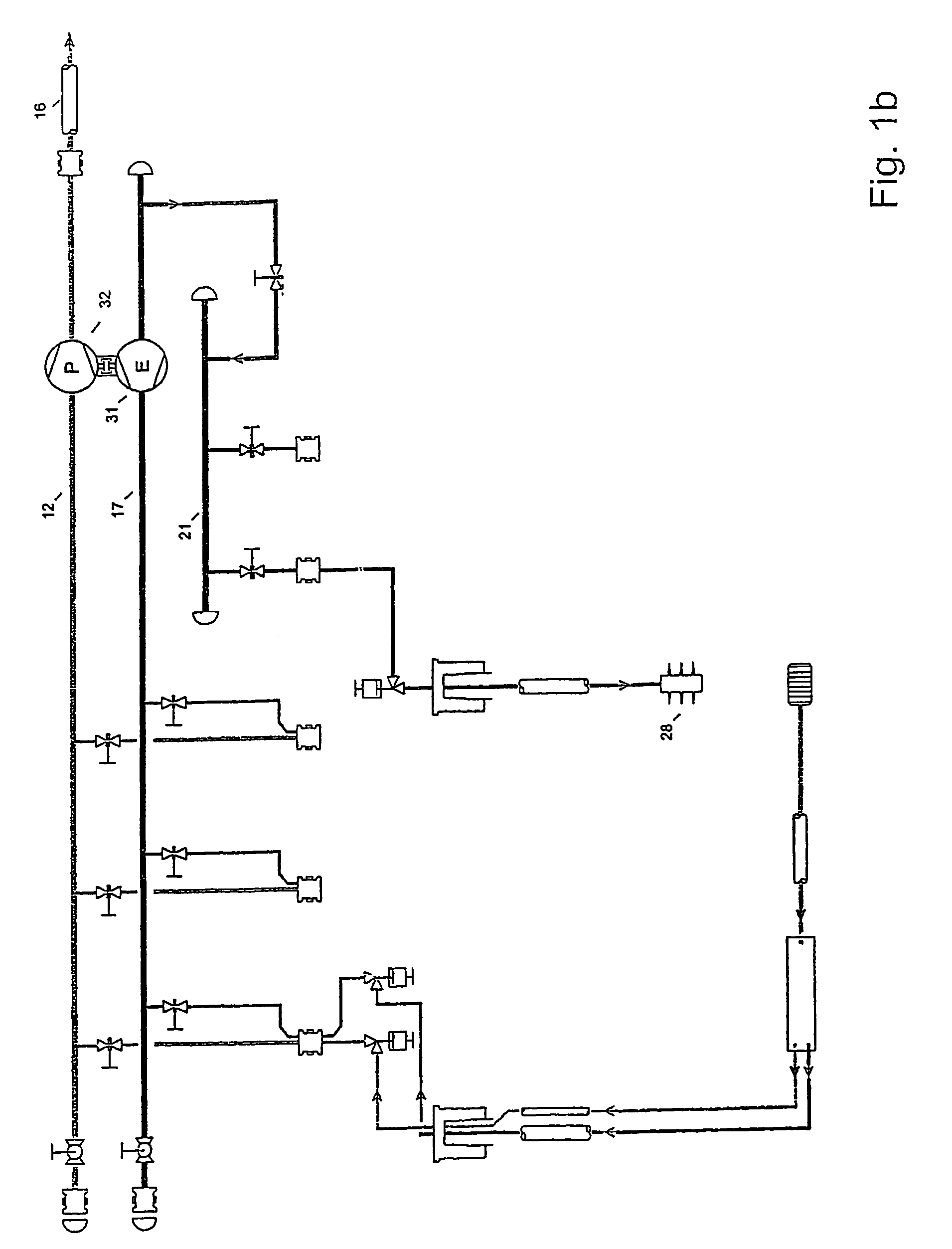
[0050]FIG. 1b illustrates a layout of a production manifold and well according to the present invention. The layout is similar to FIG. 1a, but with a turbine / pump hydraulic converter 31, 32 installed in the manifold. This layout is applicable for a production situation whereby the water phase at the seabed has a higher pressure than that which is required for injection. This available differential pressure may be utilized for pressure boosting the hydrocarbon phase.

[0051]The concept is shown with a turbine 31 installed in second header 17 and mechanically connected to a multiphase pump 32 installed into the first header 12. A by-pass and utility system is not shown, but may be present. The water flowing into the second header 17 is driving the turbine 31 into rotation, the rotation is transmitted via a shaft to the pump 32, which in turn is pressurising the hydrocarbons. This pressurising of the hydrocarbons will provide for a longer transport distance for the hydrocarbons before ad...

third embodiment

[0055]FIG. 1c illustrates a layout of a production manifold and well according to the present invention. The layout is similar to FIG. 1a, but with the implementation of a retrievable speed controlled water injection pump 29 connected to the third header 21 of the subsea manifold by a multibore connector 30. The pump 29 is illustrated without details such as utility systems, recycling arrangement and pressure equalizing valves. The produced water is fed from the second header 17, pressurized in pump 29 and discharged into the header 21 for re-injection. In addition a flowline 34 supplying additional water for re-injection may be present as shown connected to the third header 21 via a connector 33. The isolation valves 20, 35 facilitate retrieval of the injection pump.

[0056]The feasibility of this concept requires that the water phase can be brought from the formation to the suction side of the pump 29 with a net positive suction head in excess of what is required to avoid cavitation...


PUM


Abstract

A method utilizes the energy of water that flows out from a high-pressure reservoir. Water and hydrocarbons are separated in a down-hole separator and are brought separately to the seabed. In a first aspect the energy of the water is utilized to inject the water into an underground formation with a lower pressure. In a second aspect the energy is utilized to drive a turbine which in turn is driving a pump for pressurizing hydrocarbons. The invention utilizes a method and an arrangement to control the separator by control valves on the well head for each phase.

Description

RELATED APPLICATIONS[0001]The application is a National Stage of International Application No. PCT / NO01 / 00421, file Oct. 22, 2001, which published in the English language and is an international filing of Norway Application No. 20005318, filed on Oct. 20, 2000. Priority is claimed.FIELD OF THE INVENTION [0002]The present invention relates to downhole separation of hydrocarbons and water followed by discrete (separate) transportation of the fluids to a subsea wellhead for further processing, especially avoiding use of downhole rotating machinery as far as possible. The invention relates in a first aspect to utilisation of the pressure energy in the water phase for injection into an underground formation. In a second aspect the invention relates to utilisation of the pressure energy of the water phase or the hydrocarbon phase to power equipment on the seabed. It relates in a third aspect to a method of controlling the downhole separator. In a fourth aspect it relates to a method and a...

Claims


Application Information

Patent Timeline
Patent Type & Authority Patents(United States)
IPC IPC(8): E21B43/36E21B43/12E21B43/38
CPCE21B43/121E21B43/385E21B43/129
Inventor OLSEN, GEIR INGEHOMSTVEDT, GUNDER
Owner AKER SUBSEA LTD
Why Eureka
Try Eureka