Current transfer logic

a current transfer logic and transmission line technology, applied in logic circuit coupling/interface arrangement, baseband system details, pulse techniques, etc., can solve the problems of limiting the lvds system, noise and the loss of 250 mv represents a noise margin at the driver and attenuation. , to achieve the effect of speed, power, noise and jitter

Inactive Publication Date: 2006-12-26
SEMICON COMPONENTS IND LLC
View PDF19 Cites 12 Cited by
  • Summary
  • Abstract
  • Description
  • Claims
  • Application Information

AI Technical Summary

Benefits of technology

[0015]In view of the foregoing background discussion, the present invention provides a current mode transfer logic transmission line driver system and method. The inventive system provides two transmission lines each driven from unbalanced or unequal current sources. The unequal current sources are switched between the two transmission lines in response to a logic signal. The distal ends of the transmission lines share a termination resistor arranged between their signal carrying conductors. The unequal currents are sensed at the distal end, and when the unequal currents are switched between the transmission lines, a different logic state is detected. The current mode driving and current sensing at the distal ends of the transmission lines, compared to voltage sensing, provide, at least, speed, power, noise and jitter advantages.

Problems solved by technology

But as speeds increased and more circuitry is placed on chips, difficulties in driving capacitance, noise, jitter and power levels become issues that have spawned other techniques.
The lost 250 mV represents a noise margin at the driver and attenuation due to the transmission line.
Other problems limit the LVDS system.
Prior art designs sense that voltage with a high gain amplifier, but the slew rate of the voltage signal is limited by the I / C, where C may be considerable since it is the capacitance related to the high gain amplifier required by the LVDS approach.
Current drivers for transmission lines are known, but such systems often use a voltage sensing across the termination resistor, and as such, suffer from many of the same problems associated with high gain voltage receiving amplifiers.
If imbalances occur, the voltage across the Rt may be offset which may negatively affect the sensing circuit operation.

Method used


Image

  • Current transfer logic
  • Current transfer logic
  • Current transfer logic

Examples


Embodiment Construction

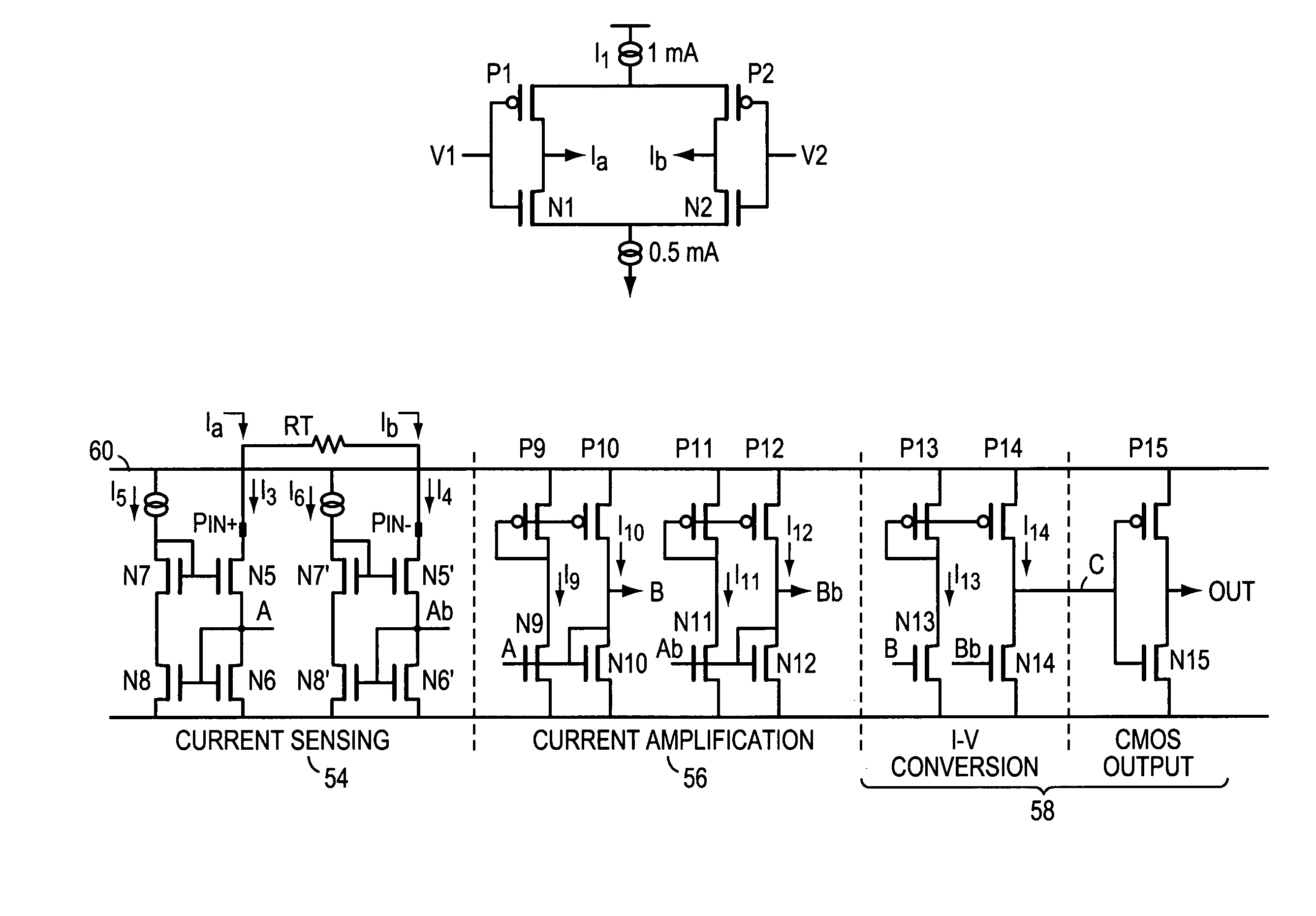
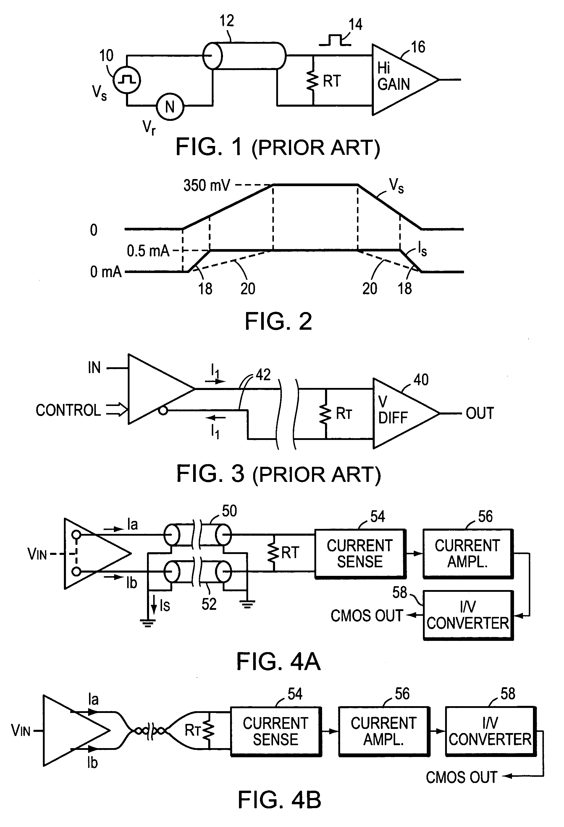
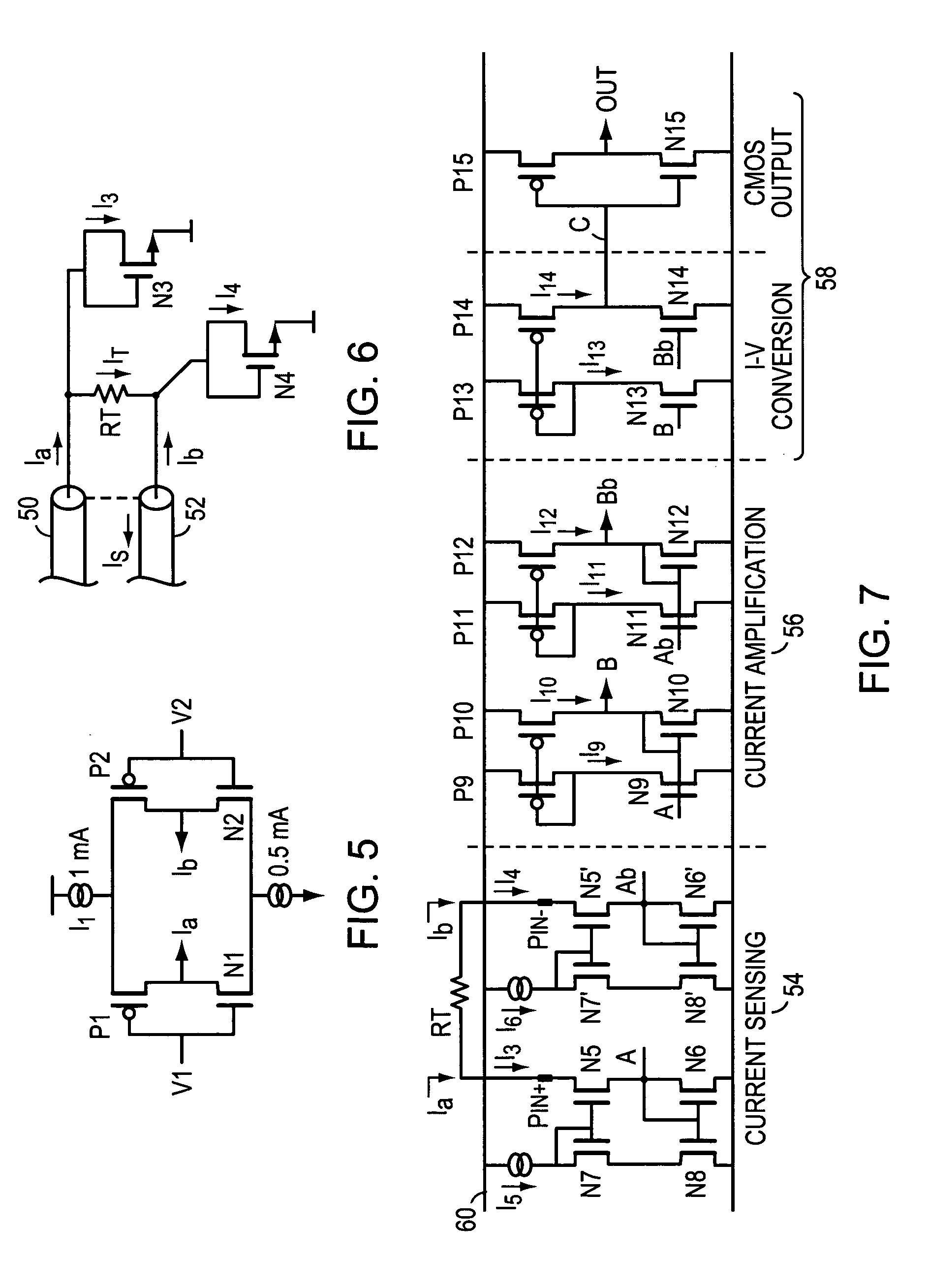
[0027]FIG. 4A shows a diagram of a preferred embodiment of the present invention. An input signal, Vin controls and selects output current signals Ia and Ib that are driven into the transmission lines 50 and 52. In one logic state, Ia is a positive current out into a first transmission line 50 and Ib is a negative current in from a second transmission line 52. In the opposite logic state, Ia is a negative current from the first transmission line 50 and Ib is a positive current into the second transmission line 52. In another preferred embodiment, it is possible to have no current driven into either transmission line.

[0028]If each transmission line has a characteristic impedance of 50 ohms, a 100 ohm Rt is placed across the distal ends of the signal conductors and serves to terminate both lines. Of note is that Ia and Ib are not equal to each other so that there will be a return current through the shield. Also, since Rt is across the distal ends of both transmission lines, both ends...


PUM


Abstract

A current mode transfer logic system suitable for driving transmission lines is disclosed. In one embodiment a twisted pair transmission line is terminated in its characteristic line impedance. A signal is formed of two unequal currents, preferably of different polarities as well as magnitudes, that are driven down the two lines. The unequal currents are selectively switched between the two lines creating a logic signal of a differential current drive of unequal current magnitudes. The unequal currents are received and shunted from the distal end of each line via diode connected MOS transistors. The MOS transistors are biased to present a low impedance, but an impedance higher than the terminating resistor. The currents are amplified and converted to useable CMOS voltage levels. In another embodiment the twisted pair is replaced by two parallel transmission lines which are terminated in one resistor, equal to the sum of the characteristic impedances of each line. The terminating resistor is connected between the distal signal carrying conductors of each transmission line. The shields or return paths for each line are tied together at the distal and at the proximate (drive) ends of the line.

Description

BACKGROUND OF THE INVENTION[0001]1. Field of the Invention[0002]The present invention relates to sending logic signals over terminated transmission lines, and more particularly to sending differential signals over transmission lines.[0003]2. Background Information[0004]Sending logic (and analog) signals over transmission lines while maintaining the fidelity by impedance matching of such signals has been of interest in many technical fields, especially in communications and computer systems, for many years. This area has become increasingly important as system speeds increase and power dissipation requirements decrease.[0005]In logic and computer systems, transmission line drivers typically began by transmitting unipolar logic (voltage) signals over matched transmission lines. Types of transmission lines used in such systems include, but are not limited to, single and paired wires, twisted pairs, shielded twisted pairs, flat cables, flat cables with a ground shield, and coaxial. The ...

Claims


Application Information

Patent Timeline
Patent Type & Authority Patents(United States)
IPC IPC(8): H03K5/22H03K5/153H04L25/02
CPCH04L25/0272H04L25/0282H04L25/0294H04L25/0278H04L25/02H04B3/54H04B3/00
Inventor PRADHAN, PRAVASJU, JIANHONG
Owner SEMICON COMPONENTS IND LLC
Why Eureka
Try Eureka