Numeric control method and numeric control system

a control method and numerical control technology, applied in the field of numerical control, can solve problems such as the inability to check the dead time presence or timing check between systems, the cycle time may be longer, and the suspension of program execution

Inactive Publication Date: 2006-12-26
MITSUBISHI ELECTRIC CORP
View PDF8 Cites 26 Cited by
  • Summary
  • Abstract
  • Description
  • Claims
  • Application Information

AI Technical Summary

Benefits of technology

[0022]This invention has been achieved to solve the above-mentioned problems, and it is an object of the invention to provide a numerical control method and a numerical control system in which a non-operation time necessarily occurring with an NC apparatus is eliminated.
[0023]Also, it is another object of the invention to provide a numerical control method and a numerical control system in which the machine controls efficiently.
[0024]Also, it is another object of the invention to provide a numerical control method and a numerical control system in which the machine life is lengthened.

Problems solved by technology

Though the interrupt itself has almost no influence on the processed face, the cycle time may be longer if the short time is accumulated.
Since the analysis processing time of a macro program is long, a program execution suspension occurs due to an interrupt of upper-level task.
Though the dead time is only small, in the so-called program check, the tool locus may be checked, but the dead time presence check or the timing check between systems can not be made.
Also, since the dead time is not resolved by the simple edit or programming method, those problems were left unsolved.

Method used


Image

  • Numeric control method and numeric control system
  • Numeric control method and numeric control system
  • Numeric control method and numeric control system

Examples


embodiment 1 (

Description for Overall Configuration and Automatic Deletion of Dead Time)

[0054]Referring to FIGS. 1 to 7, an embodiment 1 of the present invention that is applied to a dual system lathe will be described below.

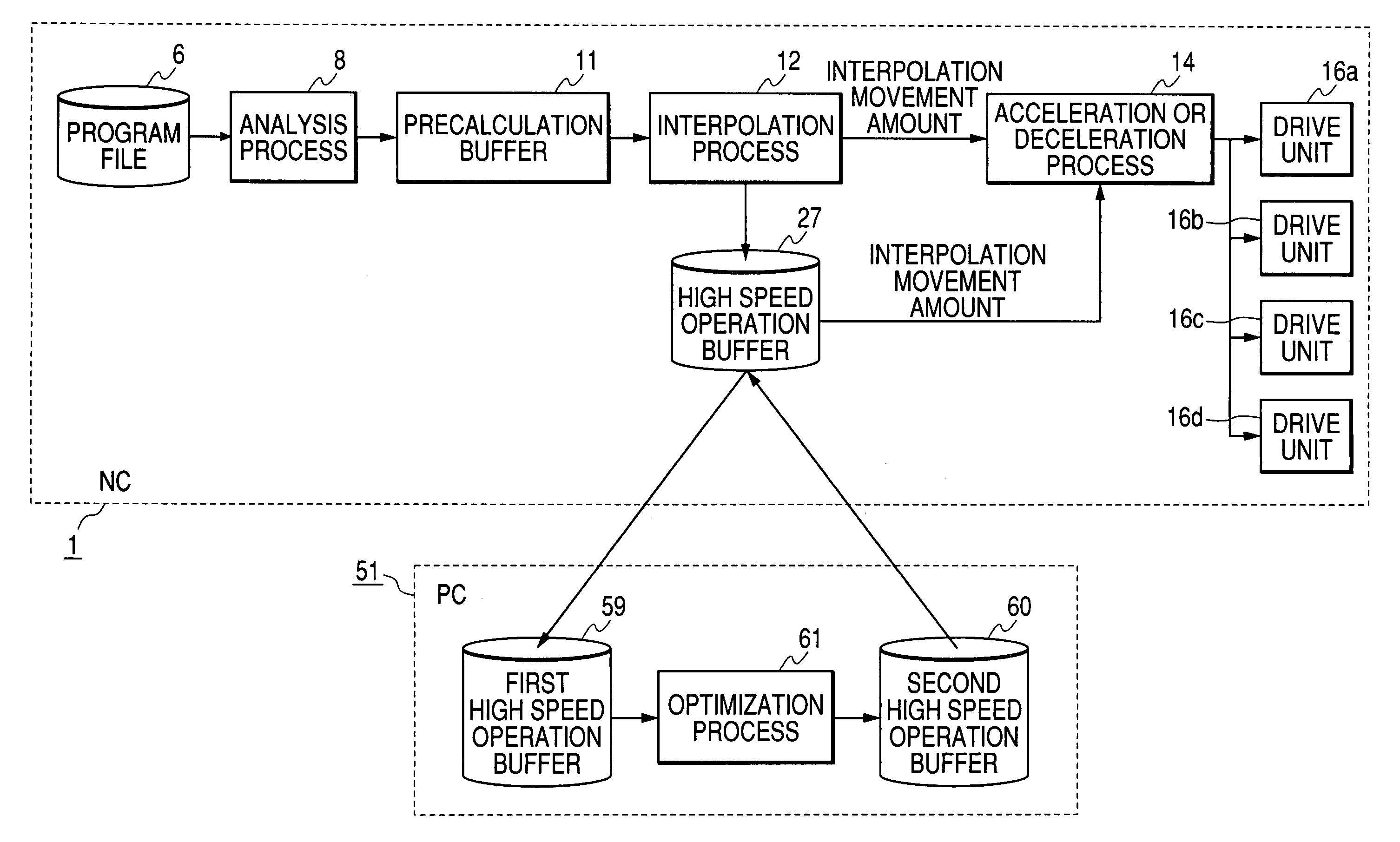
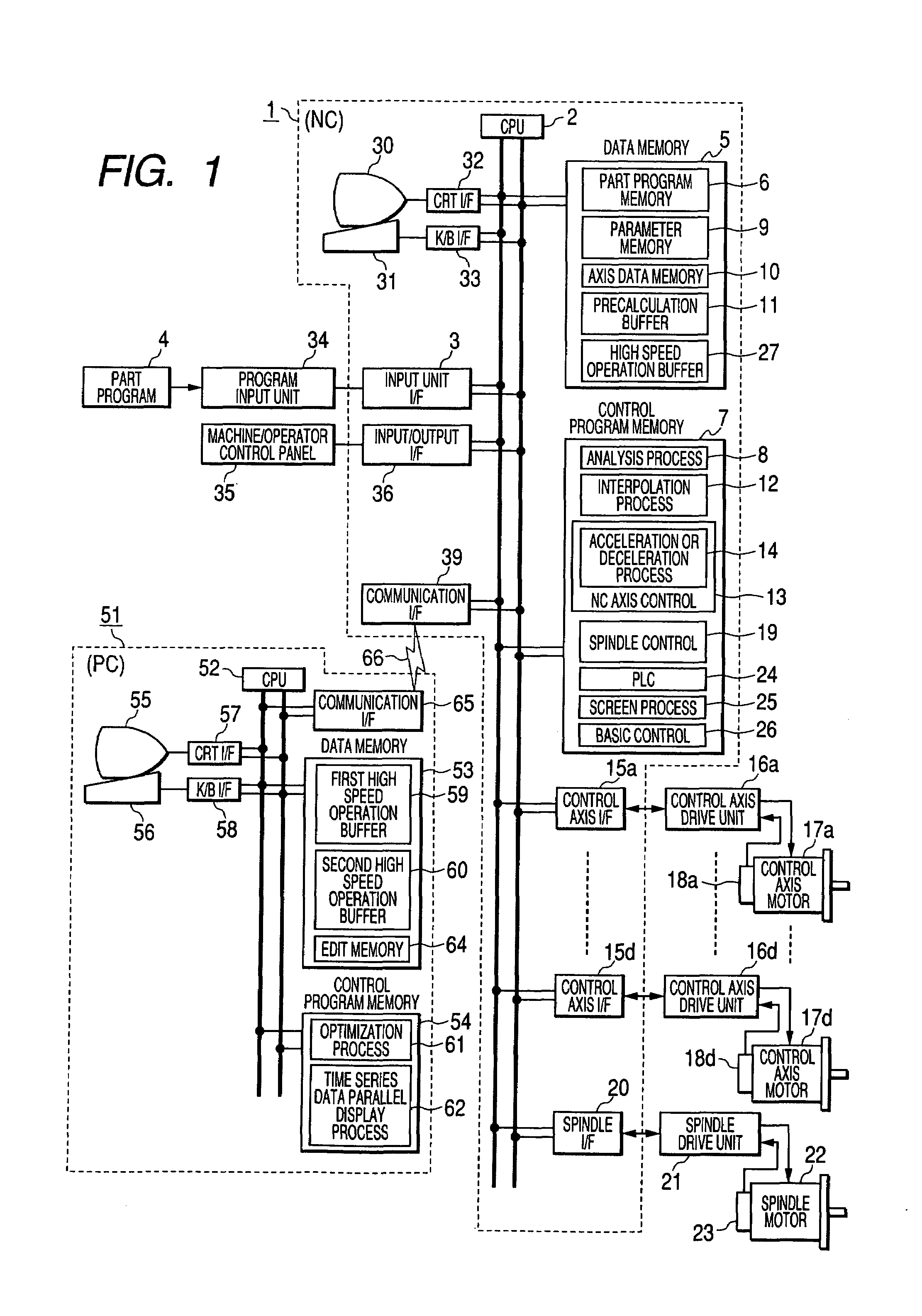
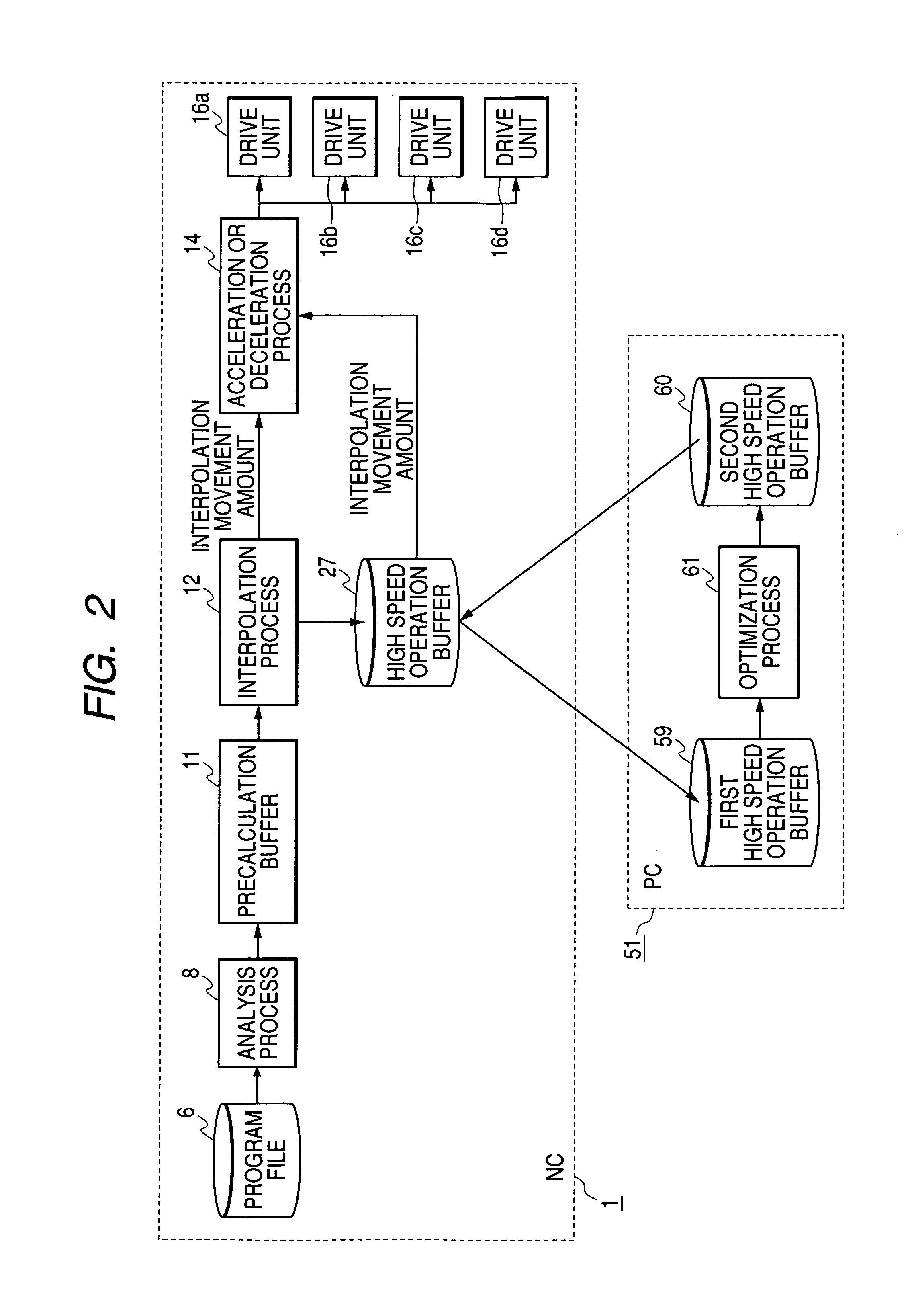
[0055]FIG. 1 is a block diagram showing the configuration of an NC system according to the embodiments 1 to 3 of the invention. FIGS. 2 and 3 are block diagrams showing the data flow of the essence of FIG. 1.

[0056]In FIGS. 1 to 3, reference numeral 1 denotes an NC apparatus, 2 denotes a CPU, 3 denotes an input unit I / F, 4 denotes a part program, and 5 denotes a data memory having a part program memory 6, a precalculation buffer 11, a parameter memory 9, an axial data memory 10 and a high speed operation buffer 27. Reference numeral 7 denotes a control program memory storing an analysis processing part 8, an interpolation processing part 12, an acceleration or deceleration processing part 14, an NC axis controlling part 13, a spindle controlling part 19, a PLC (Programmable Lo...

embodiment 2 (

Non-Interpolation Axis Shift)

[0102]Referring to FIG. 1, FIGS. 3 and 4, and FIGS. 8 to 10, an embodiment 2 of the invention will be described below.

[0103]FIGS. 8A and 8B are timing charts where the movement timing of non-interpolation axis (A axis) movement is adjusted with respect to the interpolation movement axis (X axis) of system 1. FIG. 8A shows the results of making an actual machine check for the part program, and FIG. 8B shows an example in which the end point of the non-interpolation axis of system 2 is matched with the “reference point “a”” of interpolation movement axis (X axis) of system 1 by making a shift process for changing the position of partial data in the optimization processing part 61 of the PC 51, for example, as shown in FIG. 9. The speed pattern as shown in FIG. 8A is displayed on the screen of the CRT 55, based on the data within the first high speed buffer 59. Also, the speed pattern as shown in FIG. 8B is displayed on the screen of the CRT 55, based on th...

embodiment 3

(Acceleration or Deceleration Pattern Change for Non-Interpolation Axis)

[0119]Referring to FIG. 1, FIGS. 3 and 4, and FIGS. 11 to 14, an embodiment 3 of the invention will be described below.

[0120]FIGS. 11A and 11B are timing charts for effectuating the interpolation axis of the first system and the non-interpolation axis of the second system at the same time, in which the operation form of the latter is changed in arbitrary manner. FIG. 11A shows the speed pattern of the operation upon a part program command before change. Since the execution of the non-interpolation axis (second system axis) may be completed during interpolation operation of the first system axis, as shown in FIG. 11B, the acceleration or deceleration time constant, the maximum speed and the acceleration or deceleration pattern can be changed by the optimization processing part 61 of the PC 51 under the condition where the movement amount of the second system axis is unchanged.

[0121]Referring to FIGS. 12 to 14, th...


PUM


Abstract

A numerical control system comprises a high speed operation buffer 27 for storing all the NC control data (interpolation movement amount or acceleration or deceleration data, etc.) occurring in time series by executing apart program, a time series data parallel display part 62 for reading and displaying the data in time series, an optimization processing part 61 for making the edit process such as recalculation process to deletion of Null data, etc. and temporally shift the group of specific data or change the pattern in the group of said data, and a second high speed operation buffer 60 for storing the processing result. The series of processes are performed by a personal computer (PC) 51 connected to an NC apparatus 1 to be able to exchange data. The data stored in the second high speed operation buffer 60 is transferred to the side of the NC apparatus 1, and read and executed, whereby the optimal processing with temporal editing is performed at high speed.

Description

TECHNICAL FIELD[0001]The present invention relates to a numerical control (hereinafter referred to as an NC) method and an NC system, and more particularly to a numerical control method and an NC system in which an optimization process is performed by changing the control axis data in various ways after making an actual machine check for a part program, and the NC operation is performed based on the changed control data.BACKGROUND ART[0002]In the conventional NC apparatus, when a newly created part program is employed for processing the product, the machine is firstly not activated, but the syntax check for the program or the simulation of tool locus is made, and the machine is operated with no-load. Thereby, if there is no problem, the workpiece is mounted, processed as trial, and finally processed.[0003]Referring to FIGS. 16 and 17, the conventional NC apparatus will be described below.[0004]FIG. 16 is a block diagram of the conventional NC apparatus. In FIG. 16, reference numeral...

Claims


Application Information

Patent Timeline
Patent Type & Authority Patents(United States)
IPC IPC(8): G06F19/00G05B13/02G05B19/42G05B19/18G05B19/4093
CPCG05B19/4093G05B2219/35376G05B2219/36301Y02P90/02
Inventor SAGASAKI, MASAKAZUHARADA, TOSHIOITO, TAKASHI
Owner MITSUBISHI ELECTRIC CORP
Why Eureka
Try Eureka