Pipe insert and pipe assembly formed therewith

a technology of pipe insert and pipe assembly, which is applied in the direction of cable installation in underground tubes, insulated conductors, cables, etc., can solve the problems of cumbersome manufacturing and/or installation of available multi-channel pipelines, insufficient separation and/or shielding, and insufficient success in achieving widespread us

Inactive Publication Date: 2007-01-02
PIPELINE INSERT TECH
View PDF16 Cites 27 Cited by
  • Summary
  • Abstract
  • Description
  • Claims
  • Application Information

AI Technical Summary

Benefits of technology

[0005]It is therefore an object of the invention to provide a multi-channel pipe insert which can be easily manufactured and easily installed.
[0006]Another object of the invention is to provide a pipe insert which will enable multiple utility connections to be established through multiple channels in a single pipe while maintaining a secure and reliable separation of the utility services.
[0011]The pipe inserts and pipe assemblies of the invention have the advantage of enabling two or more utility lines or runs, such as sewer and fiber optic cable or water and fiber optic cable, or any other compatible services to be installed in a single trenching or sonic plowing operation. In addition, the pipe inserts of the invention can be used in rehabilitation of existing pipes where a flexible pipe is pulled through the existing pipeline. The pipe assemblies of the invention can also be utilized as a double containment piping system to conform to environmental regulations for double containment of certain materials.

Problems solved by technology

To date, however, such efforts have not been sufficiently successful to come into widespread use.
However, available multi-channel pipelines are cumbersome to manufacture and / or install and may not provide adequate separation and / or shielding between utility services.
Also, they are not optimally adapted to retrofitting existing utility connections.

Method used


Image

  • Pipe insert and pipe assembly formed therewith
  • Pipe insert and pipe assembly formed therewith
  • Pipe insert and pipe assembly formed therewith

Examples


Embodiment Construction

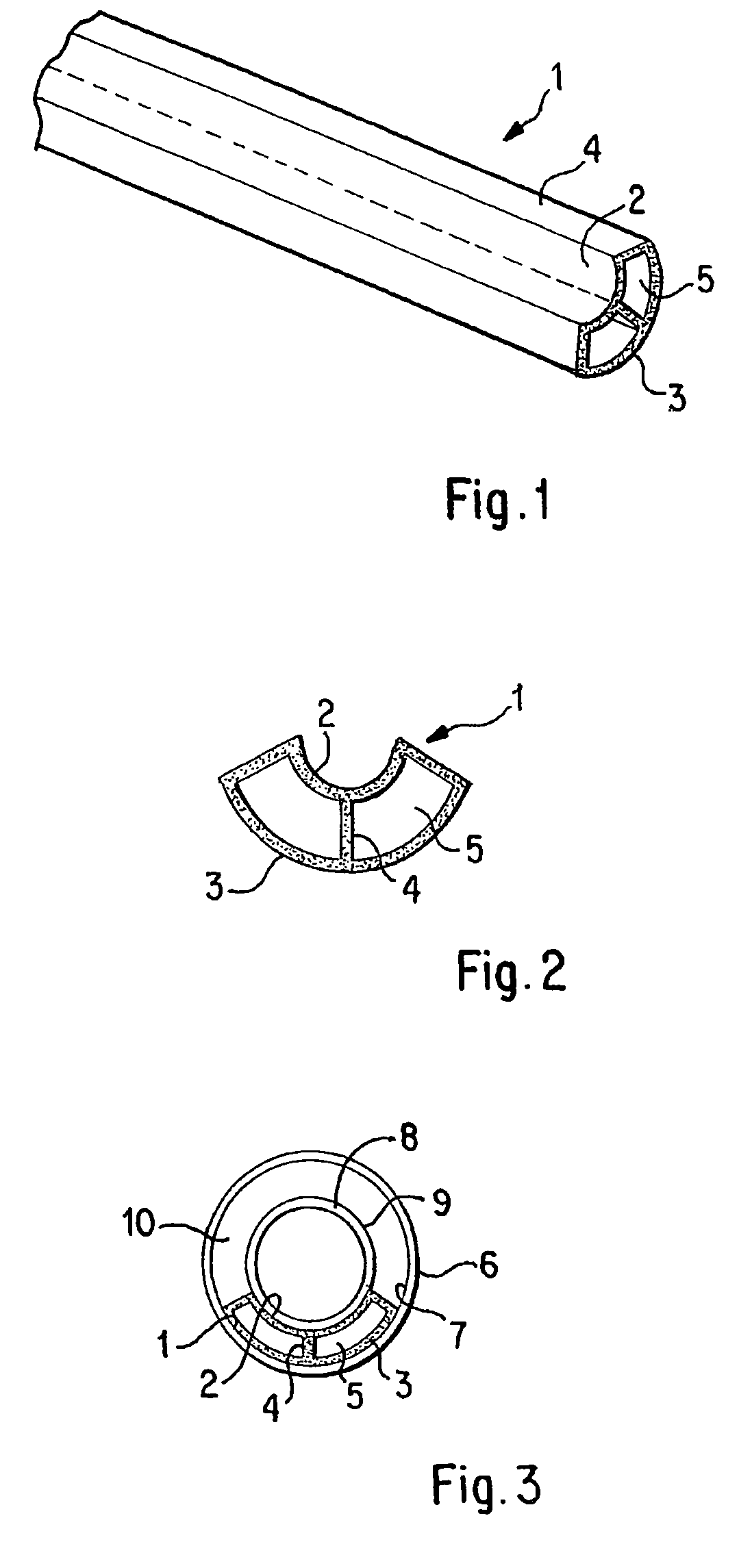
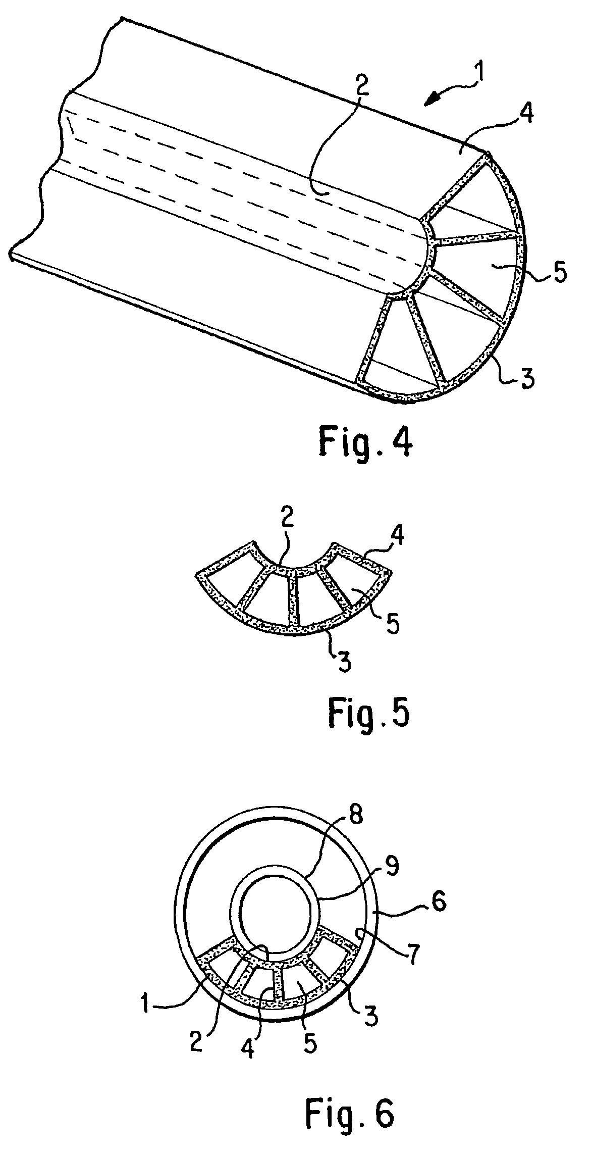
[0020]FIG. 1 is a perspective view of a pipe insert according to the invention, generally designated by reference numeral 1, having a curved cross-sectional configuration with concentric radially inner and outer walls 2 and 3 with a plurality of radial walls 4 extending between them to form a plurality of elongated channels 5. The curved cross-sectional configuration preferably forms an arc of about 60° to about 150°. It is particularly preferred to use inserts which form an arc of between about 90° and about 135° as such inserts provide the most advantageous combination of carrying capacity and ease of installation.

[0021]The pipe insert may be formed by extrusion from any suitable synthetic resin material. Suitable synthetic resin materials include polyvinyl chloride, chlorinated polyvinyl chloride, high density polyethylene, polypropylene, polyvinylidene fluoride, and acrylonitrile-butadiene-styrene, for example. If desired, the synthetic resin material from which the pipe insert ...


PUM


Abstract

A synthetic resin pipe insert for insertion in an existing pipe or for use in the manufacture of new pipe to form a multi-channel pipe. The insert has a curved cross sectional configuration which defines a segment of a circle with a convexly curved radially outer wall and a concavely curved radially inner wall and a plurality of radial walls extending between the curved, radially inner and outer walls to form at least two linear channels. A curved inner pipe member may optionally be fitted against the concavely curved radially inner wall. The pipe insert of the invention facilitates multiple utility connections, such as cable TV and sewer, in a single pipe assembly.

Description

BACKGROUND OF THE INVENTION[0001]Buildings typically require multiple utility connections. For example, it is usual to have one connection for water supply, another for conveying away sewage, a third for electricity, a fourth for telephone, a fifth for cable television, and a sixth for a heating fuel, such as natural gas. Additional types of connections, such as for dedicated data processing networks, may also be envisioned. It is usual for each connection to be established separately. Moreover, there is an increasing tendency for such connections to be established underground. Not only do underground connections avoid the undesirable aesthetic effects of visible above-ground connections, but they also in many cases are more protected against disturbance due to freezing, falling trees, or other causes.[0002]The installation of separate underground connections for each utility service multiplies the work required as well as requiring extra space so that the connections can be far eno...

Claims


Application Information

Patent Timeline
Patent Type & Authority Patents(United States)
IPC IPC(8): F16L9/18F16L7/00F16L9/19H02G9/06
CPCF16L7/00H02G9/06F16L9/19
Inventor TOPEK, PHILIP R.ROLLINS, NEWELL J.
Owner PIPELINE INSERT TECH
Why Eureka
Try Eureka