
Low relative intensity noise fiber grating type laser diode

a laser diode and fiber grating technology, applied in the field of laser sources, can solve the problems of increasing the challenges inherent in optical amplifier design, limiting the dynamic range of output power of the raman optical amplifier, and affecting the performance so as to reduce the relative intensity noise of the fiber grating and reduce the relative intensity noise of the laser diode

Active Publication Date: 2007-01-02
LUCENT TECH INC
View PDF7 Cites 9 Cited by
  • Summary
  • Abstract
  • Description
  • Claims
  • Application Information

AI Technical Summary

Benefits of technology

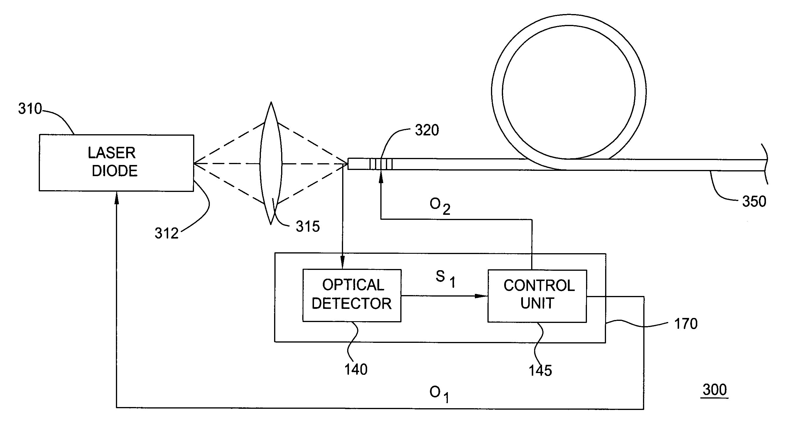
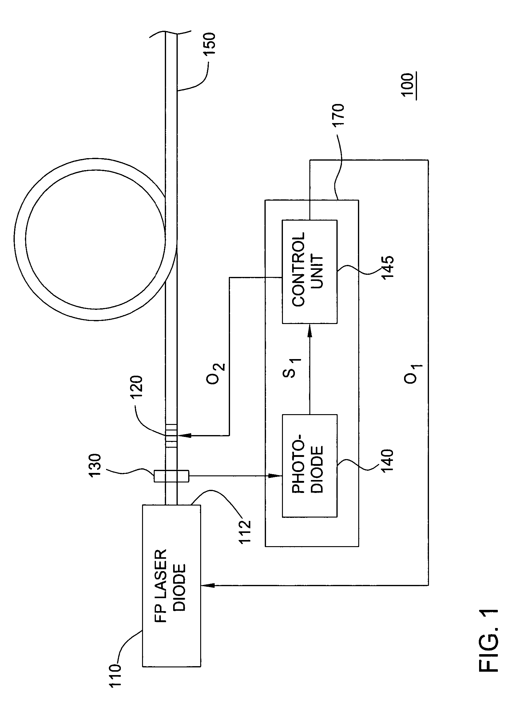
[0006]In one embodiment of the present invention, a method for reducing the relative intensity noise of a fiber grating type laser diode having a fiber grating and a laser diode includes detecting a reflected portion of an optical signal of the laser diode, the reflected portion of the optical signal being reflected by the fiber grating, determining, from the detected optical signal, the relative intensity noise of the laser diode and reducing a difference between a maximum gain wavelength of the laser diode and a maximum reflection wavelength of a fiber grating of the fiber grating type laser diode in a manner tending to reduce the relative intensity noise of the fiber grating type laser diode.
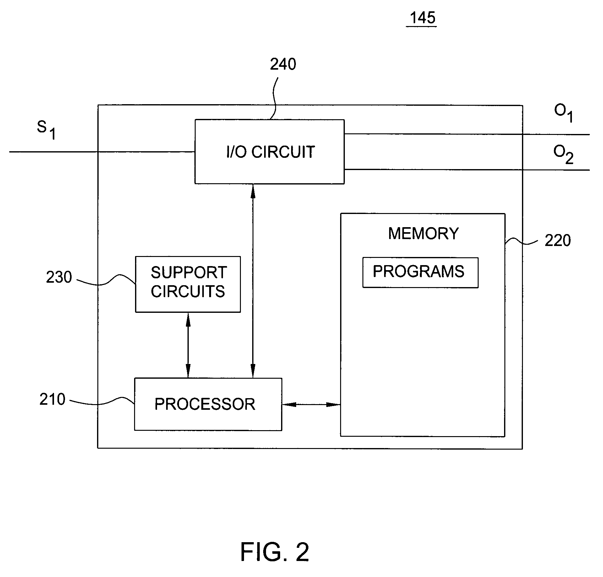
[0007]In an alternate embodiment of the present invention, a relative intensity noise (RIN) control device for controlling the RIN of a fiber grating type laser diode having a fiber grating and a laser diode includes an optical detector for detecting a reflected portion of an optical signal of the laser diode, the reflected portion of the optical signal being reflected by the fiber grating, and a control unit having a memory for storing information and program instructions and a processor for executing the instructions, the control unit adapted to perform the steps of determining, from the detected optical signal, the relative intensity noise of the laser diode, and reducing a difference between a maximum gain wavelength of the laser diode and a maximum reflection wavelength of the fiber grating in a manner tending to reduce the relative intensity noise of said laser diode.
[0008]In yet an alternate embodiment of the present invention, a relative intensity noise (RIN) controlled fiber grating type laser diode includes a laser diode for providing an optical signal, a fiber grating for reflecting at least a portion of the optical signal back toward the laser diode, an optical detector for detecting the reflected portion of the optical signal of the laser diode, and a control unit having a memory for storing information and program instructions and a processor for executing the instructions. The control unit is adapted to perform the steps of determining, from the detected optical signal, the relative intensity noise of the laser diode, and reducing the difference between the maximum gain wavelength of the laser diode and the maximum reflection wavelength of the fiber grating in a manner tending to reduce the relative intensity noise of the laser diode.

Problems solved by technology

Continuing development of WDM systems including DWDM (dense WDM) systems is increasing the challenges inherent in optical amplifier design.
Amplifying such DWDM signals is problematic for a number of reasons.
For example, if an unstabilized pump laser is used for pumping a Raman optical amplifier used for amplifying DWDM signals, the amplification range of the Raman optical amplifier will be limited by the limited dynamic range of the output power of the unstabilized pump laser.
As such, the power of an unstabilized pump laser must remain substantially constant, which results in a limited dynamic range.
The relative intensity noise (RIN) of such stabilized lasers, however, is often insufficient for the stringent requirements of high speed and high density optical systems and applications.

Method used


Image

  • Low relative intensity noise fiber grating type laser diode
  • Low relative intensity noise fiber grating type laser diode
  • Low relative intensity noise fiber grating type laser diode

Examples


Embodiment Construction

[0014]Although various embodiments of the present invention are being described herein with respect to fiber grating stabilized laser diodes, the specific embodiments of the present invention described herein should not be treated as limiting the scope of the invention. It will be appreciated by those skilled in the art informed by the teachings of the present invention, that the concepts of the present invention may be applied in substantially any laser system having a fiber grating and for substantially any application wherein a laser having low relative intensity noise is desirable.

[0015]Fiber grating wavelength stabilized lasers typically comprise a laser diode, a focusing system, a fiber grating (typically a Fiber Bragg Grating) and a transmission fiber. The laser diode is pumped by current injection and is configured to emit radiation primarily from a front facet. In such fiber grating wavelength stabilized lasers, the optical signal of the laser diode is focused and coupled t...


PUM


Abstract

The dependency of intensity noise is used to determine the wavelength difference between a laser diode gain peak and a reflection peak of a fiber grating in a fiber grating type laser diode. Monitoring and determining the relative noise intensity of such a laser enables the control of the laser diode or the fiber grating such that the intensity noise is as low as possible. Such an approach enables the use of a fiber grating type laser diode as Raman pumps in high-speed transmission systems where low intensity noise is a requirement, especially when the Raman pump power propagates in the same direction as the transmission signals (known as Raman co-pumps).

Description

FIELD OF THE INVENTION[0001]This invention relates to the field of laser sources and, more specifically, to low relative intensity noise fiber grating type laser diodes.BACKGROUND OF THE INVENTION[0002]The growth in telecommunication traffic is driving the development of technology to ever expand the available bandwidth of network communication. In particular, there is a great impetus towards increasing the capacity of optical communication links and reducing the costs of implementing capacity-increasing technologies. One method for increasing the capacity of optical communication links has been to combine optical signals with multiple wavelengths onto the same fiber, commonly referred to as wavelength division multiplexing (WDM). Essential to the development of WDM systems is the development of optical amplifier technology capable of boosting optical signals in a way that is transparent to data rate and format and that can provide effective amplification across a very large bandwid...

Claims


Application Information

Patent Timeline
Patent Type & Authority Patents(United States)
IPC IPC(8): H01S3/30H01S3/00H01S3/13H01S5/00H01S5/06H01S5/068H01S5/14H04B10/155
CPCH01S5/06H01S5/141H04B10/572H04B10/503H04B10/2519H04B10/5057H01S5/06817H01S5/1221H01S2301/02
Inventor BUCHOLD, BIANCACZOTSCHER, KONRADWERNER, DIETER
Owner LUCENT TECH INC
Learn More