Gas sensor equipped with gas inlet designed to create desired flow of gas

a gas sensor and gas inlet technology, applied in the field of gas sensors, can solve problems such as accelerated deterioration of sensor elements, and achieve the effect of reducing the concentration of thermal stress

Active Publication Date: 2007-01-09
DENSO CORP
View PDF9 Cites 12 Cited by
  • Summary
  • Abstract
  • Description
  • Claims
  • Application Information

AI Technical Summary

Benefits of technology

[0014]It is therefore an object of the invention to provide an improved structure of a gas sensor equipped with gas inlets designed to avoid a direct hit of a flow of gas to be measured on a sensor element and minimize the concentration of thermal stress around the gas inlets.
[0016]The dimple is designed to create a desired flow of gas to be measured into the cover which is oriented to avoid a direct hit of the flow of the gas on the gas sensing element and to minimize the concentration of thermal stress around the gas inlet hole.
[0018]The gas inlet hole of the outer cover is located closer than the gas inlet hole of the cover to the second end of the outer cover. This creates a flow of the gas oriented from the second end to the first end of the outer cover, thereby minimizing the possibility of a direct hit of the gas on the gas sensing element.

Problems solved by technology

Usually, exhaust gases emitted from automotive engines contain various harmful substances which result in accelerated deterioration of the sensor element 2.

Method used


Image

  • Gas sensor equipped with gas inlet designed to create desired flow of gas
  • Gas sensor equipped with gas inlet designed to create desired flow of gas
  • Gas sensor equipped with gas inlet designed to create desired flow of gas

Examples


Embodiment Construction

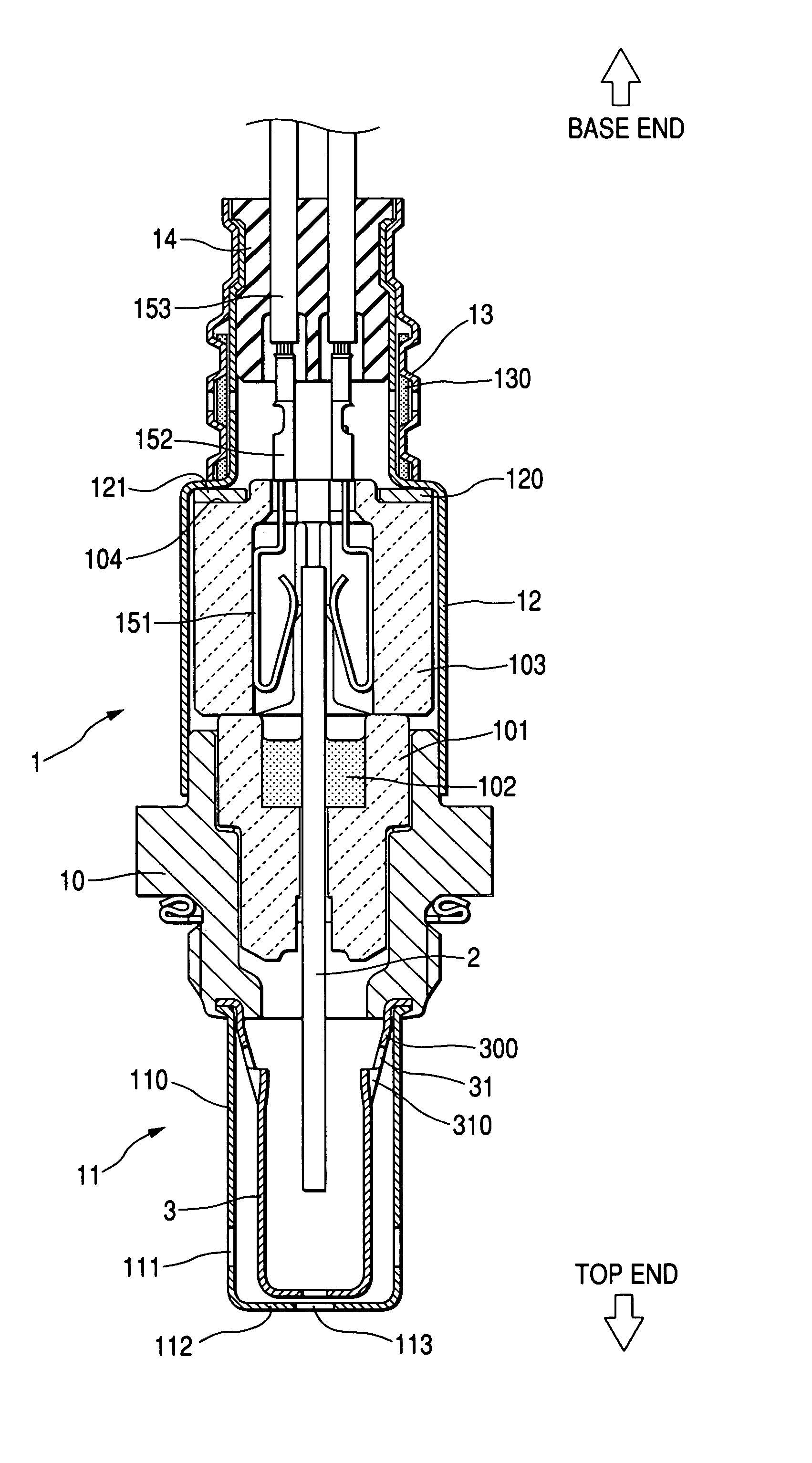
[0040]Referring to the drawings, wherein like reference numbers refer to like parts in several views, particularly to FIG. 1, there is shown a gas sensor 1 according to the first embodiment of the invention which may be employed in a burning control system for automotive engines to measure the concentration of a gas component, such as O2or NOx, contained in exhaust gasses of the engine.

[0041]The gas sensor 1 generally includes a gas sensor element 2, a hollow cylindrical housing 10, a porcelain insulator 101, and a protective cover assembly 11. The gas sensor element 2 is retained in the housing 10 through the porcelain insulator 101. The protective cover assembly 11 is secured to a top end (i.e., a lower end as viewed in the drawing) of the housing 10.

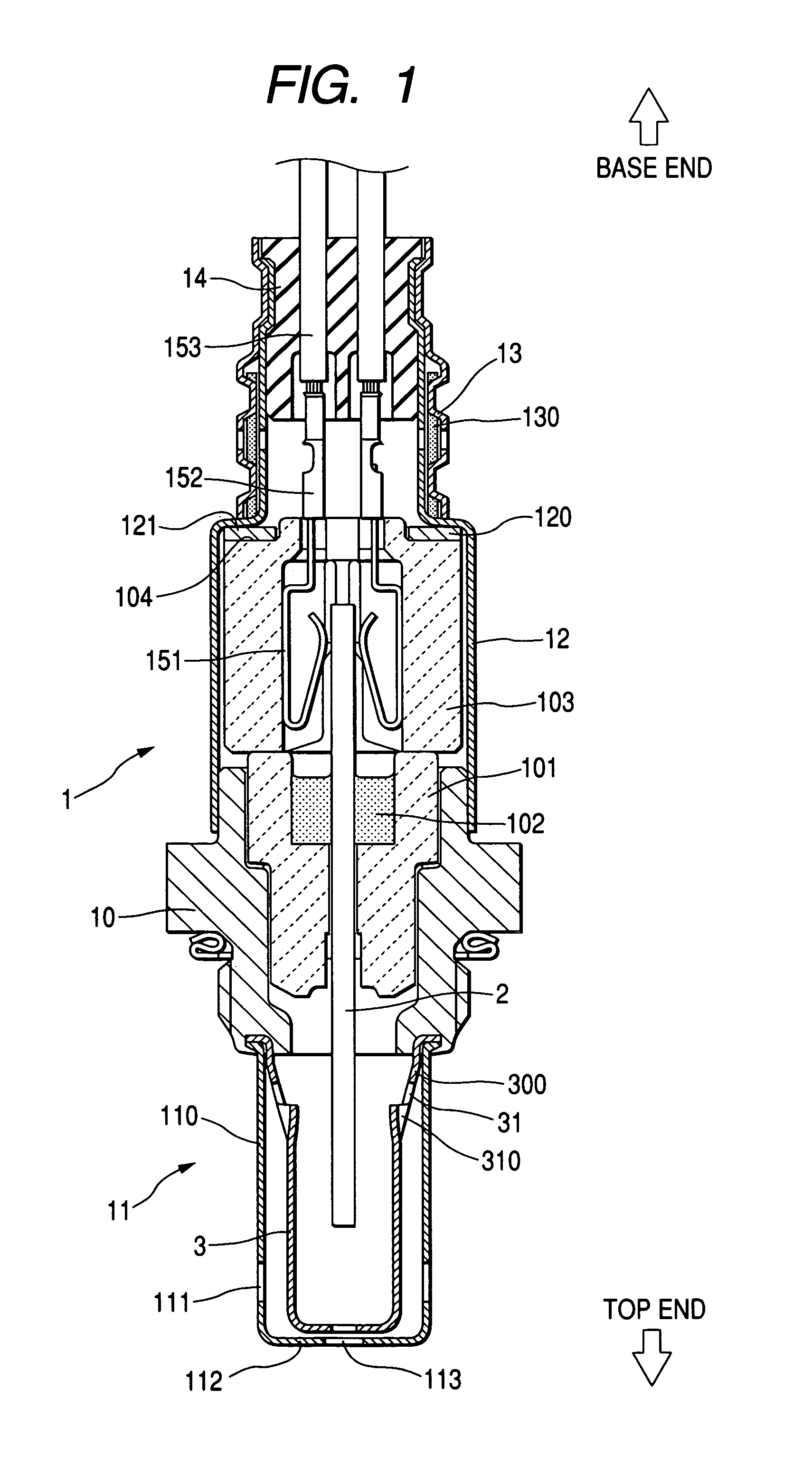
[0042]The protective cover assembly 11 has a length extending in alignment with the longitudinal center line of the gas sensor 1 (i.e., the gas sensor element 2). The protective cover assembly 11 has a double-walled structure consisti...


PUM

PropertyMeasurementUnit
diameteraaaaaaaaaa
concentrationaaaaaaaaaa
mechanical strengthaaaaaaaaaa

Abstract

A gas sensor equipped with a protective gas cover which defines therein a gas chamber to which a sensor element is exposed. The protective gas cover has gas inlet holes through which gas to be measured is admitted. The protective cover also has dimples formed adjacent the gas inlet holes, respectively, which are designed to avoid a direct hit of a flow of the gas on the sensor element and minimize the concentration of thermal stress around the gas inlet holes. In an alternative form, the gas inlet holes are formed in the dimples, respectively.

Description

CROSS REFERENCE TO RELATED DOCUMENT[0001]The present application claims the benefit of Japanese Patent Application No. 2004-37222 filed on Feb. 13, 2004, the disclosure of which is incorporated herein by reference.BACKGROUND OF THE INVENTION[0002]1. Technical Field of the Invention[0003]The present invention relates generally to a gas sensor which may be installed in an exhaust system of an internal combustion engine to determine the concentration of O2, an air-fuel ratio, or the concentration of NOx in exhaust emissions, and more particularly to an improved structure of such a type of gas sensor equipped with gas inlets designed to create a desired flow of gas to be measured and minimize the concentration of thermal stress around the gas inlets.[0004]2. Background Art[0005]Conventionally, gas sensors are used for burning control of internal combustion engines for automotive vehicles. As a typical example, a gas sensor is installed in an exhaust pipe of an automotive engine to measu...

Claims


Application Information

Patent Timeline
Patent Type & Authority Patents(United States)
IPC IPC(8): G01N27/00G01N37/00F01N11/00G01N27/409F02D41/14G01N27/403G01N27/407G01N27/416
CPCG01N27/4077
Inventor NAKAGAWA, KAZUYA
Owner DENSO CORP
Why Eureka
Try Eureka