

Modified friction control compositions
a technology of friction control and composition, applied in the direction of rail lubrication, rail wetting/lubrication, rail additives, etc., can solve the problems of uneven wear of mechanical components, high noise level of mechanical components, and many steel-rail and steel-wheel transportation systems including freight, passenger and mass transit systems, etc., to achieve enhanced retentivity
- Summary
- Abstract
- Description
- Claims
- Application Information
AI Technical Summary
Benefits of technology
Problems solved by technology
Method used
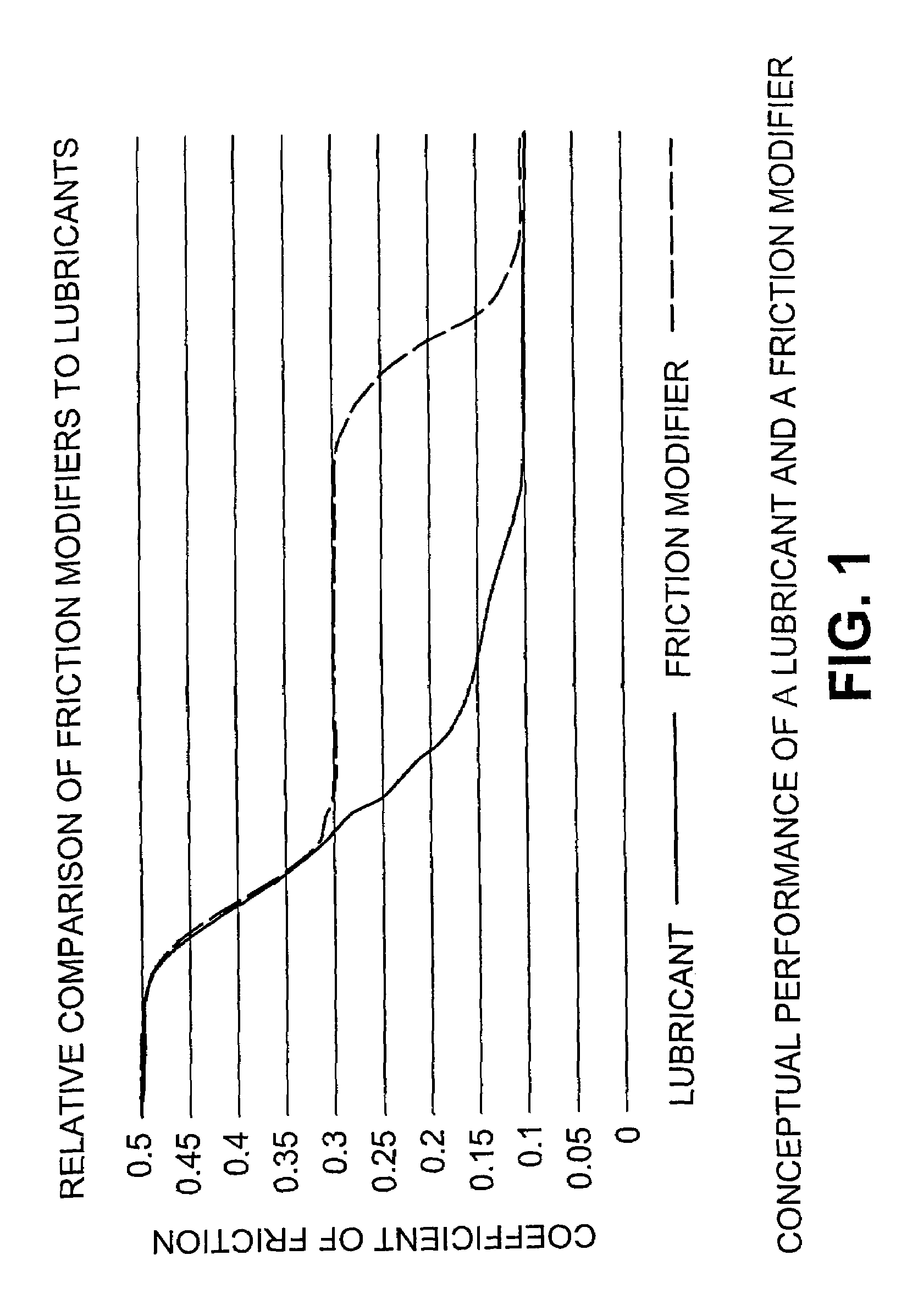
Image

Examples
example 1
Characterization of Liquid Friction Control Compositions
Amsler protocol
[0133]Retentivity may be tested using the Amsler machine. This device simulates the contact between the wheel of a train and the rail, and measures the coefficient of friction between the two bodies over time. The Amsler machine uses two different discs to simulate the wheel and rail. The two discs are kept in contact by an adjustable spring at a constant force. A composition is applied to a clean disc in a controlled manner to produce a desired thickness of coating on the disc. For the analysis disclosed herein the compositions are applied using a fine paint brush to ensure complete coating of the disc surface. The amount of applied composition is determined by weighing the disc before and after application of the composition. Composition coatings range from 2 to 12 mg / disc. The composition is allowed to dry completely prior to testing, typically for at least an 8 hour period.
[0134]The discs are loaded onto the ...
example 2
Characterization of Simplified Friction Control Compositions
Composition Comprising Lubricant Plus Friction Modifier
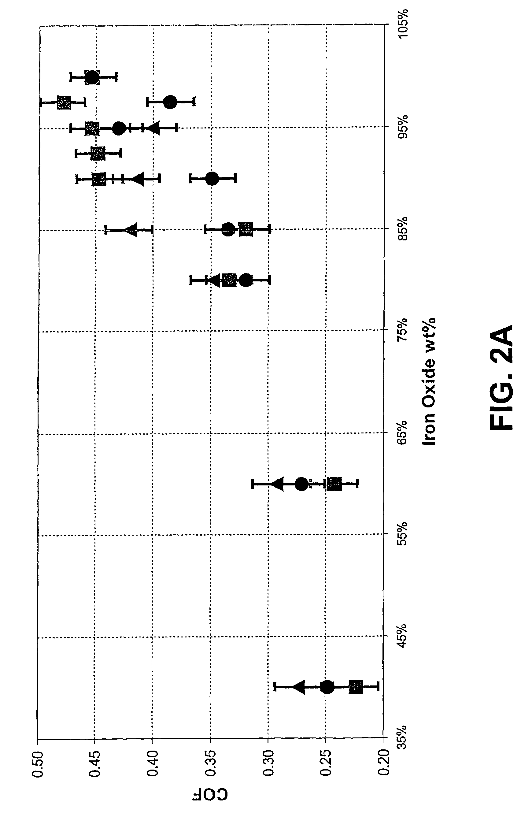
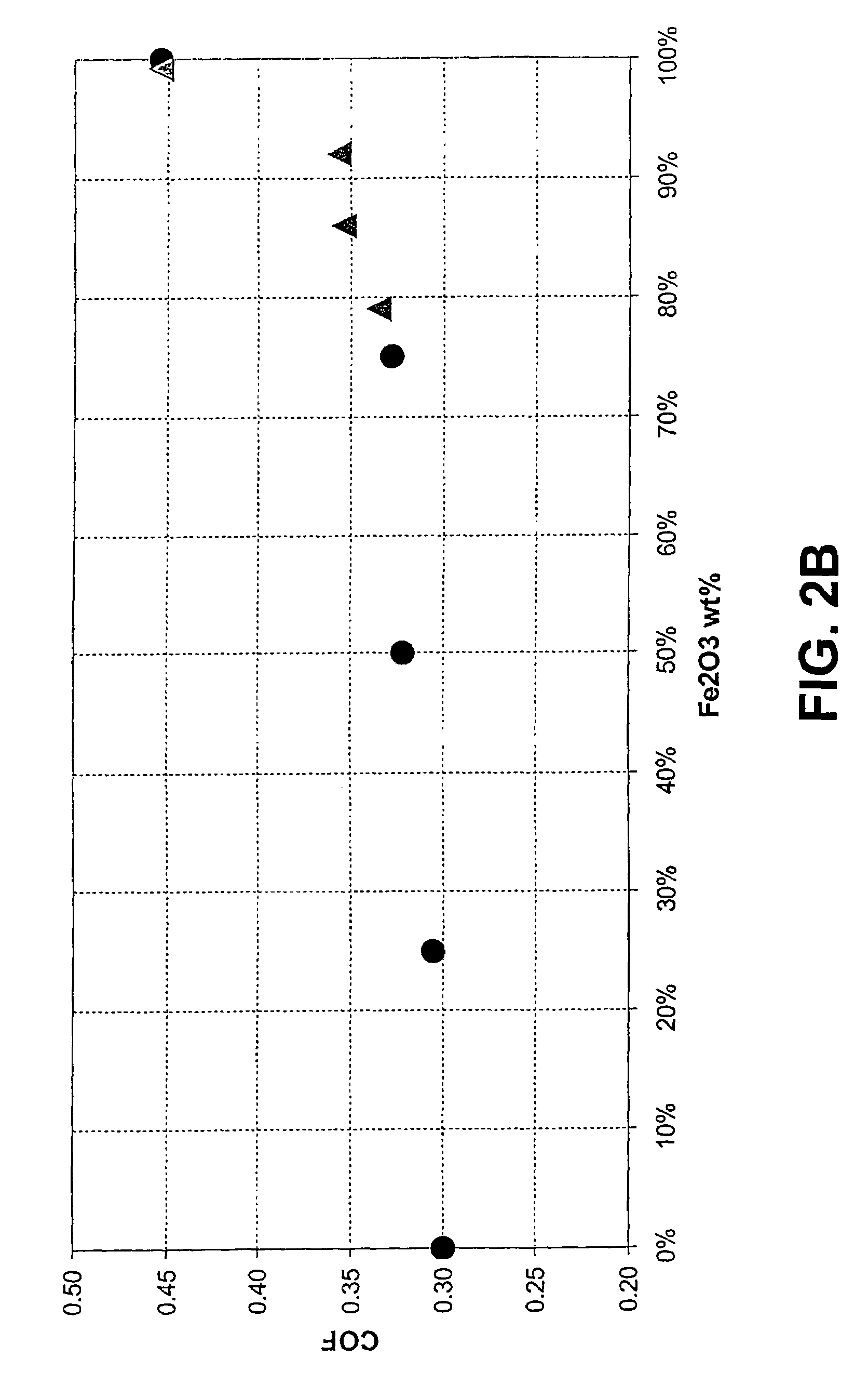
[0143]Simplified compositions comprising a lubricant (molybdenum disulfide or graphite), with or without a prior art friction modifier (talc), and varying amount of iron oxide (to simulate the surface of a rail) were prepared in water, applied to the surface of a rail, dried, and the coeffecient of friction (sliding CoF) determined using a push tribometer (H. Harrison, T. McCanney and J. Cotter (2000), Recent Developments in CoF Measurements at the Rail / Wheel Interface, Proceedings The 5th International Conference on Contact Mechanics and Wear of Rail / Wheel Systems CM 2000 (SEIKEN Symposium No. 27), pp. 30–34, which is incorporated herein by reference). The compositions comprised from 40 wt % to 98 wt % iron oxide in place of the lubricant or the lubricant and friction modifier (talc). No binder was included in these compositions.
[0144]Varying the amount of iron oxide i...
example 3
Friction Control Compositions Comprising Lubricant and Binder
Analysis of Coefficient of Friction
[0153]A set of friction control compositions comprising varying amounts of lubricant, either molybdenum disulfide or graphite, from 0 wt % to 12 wt %, and a fixed amount of binder (8.8 wt %), for example Rhoplex™ AC-264, were prepared in water and applied to the surface of a rail and the CoF (sliding CoF) determined using a push tribometer (see Example 2). The results are shown in FIGS. 3a and 3b.
[0154]In the absence of lubricant, the binder exhibits a CoF of about 0.35 (FIG. 3a), similar to that observed in Example 2 (FIG. 2b). With increasing amounts of lubricant, there is decrease in the CoF, and in composition comprising greater than about 2 wt % molybdenum disulfide, the CoF decreases below 0.3. However, compositions comprising from about 0 wt % to about 2 wt % molybdenum disulfide and 8.8 wt % binder, exhibit a CoF above 0.3. Similar results are observed in compositions comprising ...
PUM
| Property | Measurement | Unit |
|---|---|---|
| weight percent | aaaaa | aaaaa |
| wt % | aaaaa | aaaaa |
| wt % | aaaaa | aaaaa |
Abstract
Description
Claims
Application Information