Multilayer imageable element containing epoxy resin

a multi-layer, epoxy resin technology, applied in the direction of lithography, photosensitive materials, instruments, etc., can solve the problems of time-consuming process, affecting the image resolution, and the one providing one of these properties may change slightly, so as to improve image resolution, image speed, and shelf life. the effect of improvemen

Inactive Publication Date: 2007-01-09
EASTMAN KODAK CO
View PDF10 Cites 32 Cited by
  • Summary
  • Abstract
  • Description
  • Claims
  • Application Information

AI Technical Summary

Benefits of technology

[0020]The imageable elements of the present invention contain non-phenolic polymer binders in the outer layer (topcoat) that is not crosslinked but provides improved shelf life, imaging speed, and image resolution of the resulting imaged elements (for example, printing plates). These results are achieved by using an uncrosslinked epoxy-containing polymer in the outer layer that is free of hardener for the pendant epoxy groups.

Problems solved by technology

This is a time-consuming process.
In addition, dimensions of the mask may change slightly due to changes in temperature and humidity.
Thus, the same mask, when used at different times or in different environments, may give different results and could cause registration problems.
In many instances, what provides one of these properties worsens others.

Method used


Image

  • Multilayer imageable element containing epoxy resin
  • Multilayer imageable element containing epoxy resin
  • Multilayer imageable element containing epoxy resin

Examples


examples

[0105]The components and materials used in the examples and analytical methods were as follows:

[0106]MEK is methyl ethyl ketone.

[0107]DEK is diethyl ketone.

[0108]PGME is 1-methoxypropa-2-ol. It is also known as Dowanol PM.

[0109]BLO is γ-butyrolactone.

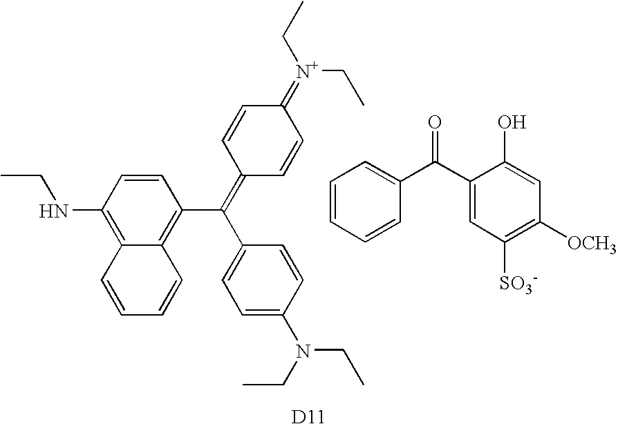
[0110]D11 dye is ethanaminium, N-[4-[[4-(diethylamino)phenyl][4-(ethylamino)-1-naphthalenyl]methylene]-2,5-cyclohexadien-1-ylidene]-N-ethyl-, salt with 5-benzoyl-4-hydroxy-2-methoxybenzenesulfonic acid (1:1) as supplied by PCAS (Longjumeau, France).

[0111]

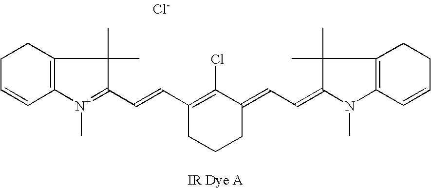
[0112]IR Dye A is an infrared absorbing dye was obtained from Honeywell (Morristown, N.J.).

[0113]

[0114]IR dye B is Kayasorb PS210CnE, an infrared absorbing dye as supplied by Nippon Kayaku Co, Ltd. (Tokyo, Japan).

[0115]IR absorbing Dye C was obtained from Eastman Kodak Company and is represented by the following formula:

[0116]

[0117]ACR-1478 is a copolymer having recurring units derived from N-phenylmaleimide (41.5 mol %), methacrylamide (37.5 mol %), and methacrylic acid (21 mol %).

[011...

examples 1 – 6

Examples 1–6

[0140]Imageable elements containing the various epoxy-containing polymers described herein in the outer (top) layer were prepared as follows:

[0141]Inner layer formulations were prepared with the components described in TABLE IV below and applied to Substrate A using a 0.012 inch (0.03 cm) wire-wound bar and dried for 30 seconds at 135° C. to provide a dry coated film of approximately 1.5 g / cm2.

[0142]Topcoat (outer layer) solutions were prepared with the components described in TABLE V below and applied with a 0.006 inch (0.015 cm) wire-wound bar and dried at 30 seconds at 135° C. to provide a dry coat weight of approximately 0.60 g / cm2.

[0143]

TABLE IVInner Layer Formulations Based on 80 g of Coating Solution with 7.0% Non-volatilesBYK30710% solutionJK69ACR1478IR Dye AIR Dye BIR Dye Cin DEKSolvent*Inner Layer A4.55600.56000.4500.36474.072Inner Layer B04.55600.5600.4500.36474.072*Solvent mixture - MEK / PGME / BLO / water 50 / 30 / 10 / 10 by weight.

[0144]

TABLE VUpper Layer Formulation...


PUM

PropertyMeasurementUnit
weight %aaaaaaaaaa
weight %aaaaaaaaaa
weight %aaaaaaaaaa

Abstract

A positive-working imageable element comprises inner and outer layers and a radiation absorbing compound such as an IR absorbing dye. The inner layer includes a polymeric material that is removable using an alkaline developer. An ink receptive outer layer is not removable using an alkaline developer before its exposure to imaging radiation. The outer layer includes a polymer binder having pendant epoxy groups that are substantially unreacted during exposure.

Description

FIELD OF THE INVENTION[0001]This invention relates to positive-working imageable elements having improved shelf life that can be used to form positive-working lithographic printing plates with improved image resolution. It also relates to a method of forming imaged elements from such imageable elements using thermal imaging means.BACKGROUND OF THE INVENTION[0002]In conventional or “wet” lithographic printing, ink receptive regions, known as image areas, are generated on a hydrophilic surface. When the surface is moistened with water and ink is applied, the hydrophilic regions retain the water and repel the ink, and the ink receptive regions accept the ink and repel the water. The ink is transferred to the surface of a material upon which the image is to be reproduced. For example, the ink can be first transferred to an intermediate blanket that in turn is used to transfer the ink to the surface of the material upon which the image is to be reproduced.[0003]Imageable elements useful ...

Claims


Application Information

Patent Timeline
Patent Type & Authority Patents(United States)
IPC IPC(8): G03F7/11G03F7/038G03F7/14
CPCB41C1/1016B41M5/368Y10S430/106Y10S430/165Y10S430/111B41C2210/262B41C2210/06B41C2210/14B41C2210/22B41C2210/24B41C2210/02
Inventor HUANG, JIANBINGSARAIYA, SHASHIKANTRAY, KEVIN B.KITSON, ANTHONY P.SHERIFF, EUGENE L.KREBS, ANDREW
Owner EASTMAN KODAK CO
Why Eureka
Try Eureka