
Housing for a thin active probe

a technology of active probes and housings, which is applied in the direction of coupling device connections, instruments, diagnostic recording/measuring, etc., can solve the problems of small power dissipation of probes, relatively high cost, and simple inability to fit probes into the available space, etc., and achieves high aspect ratio of width and use. , the effect of high aspect ratio

Inactive Publication Date: 2007-01-16
AGILENT TECH INC
View PDF5 Cites 18 Cited by
  • Summary
  • Abstract
  • Description
  • Claims
  • Application Information

AI Technical Summary

Benefits of technology

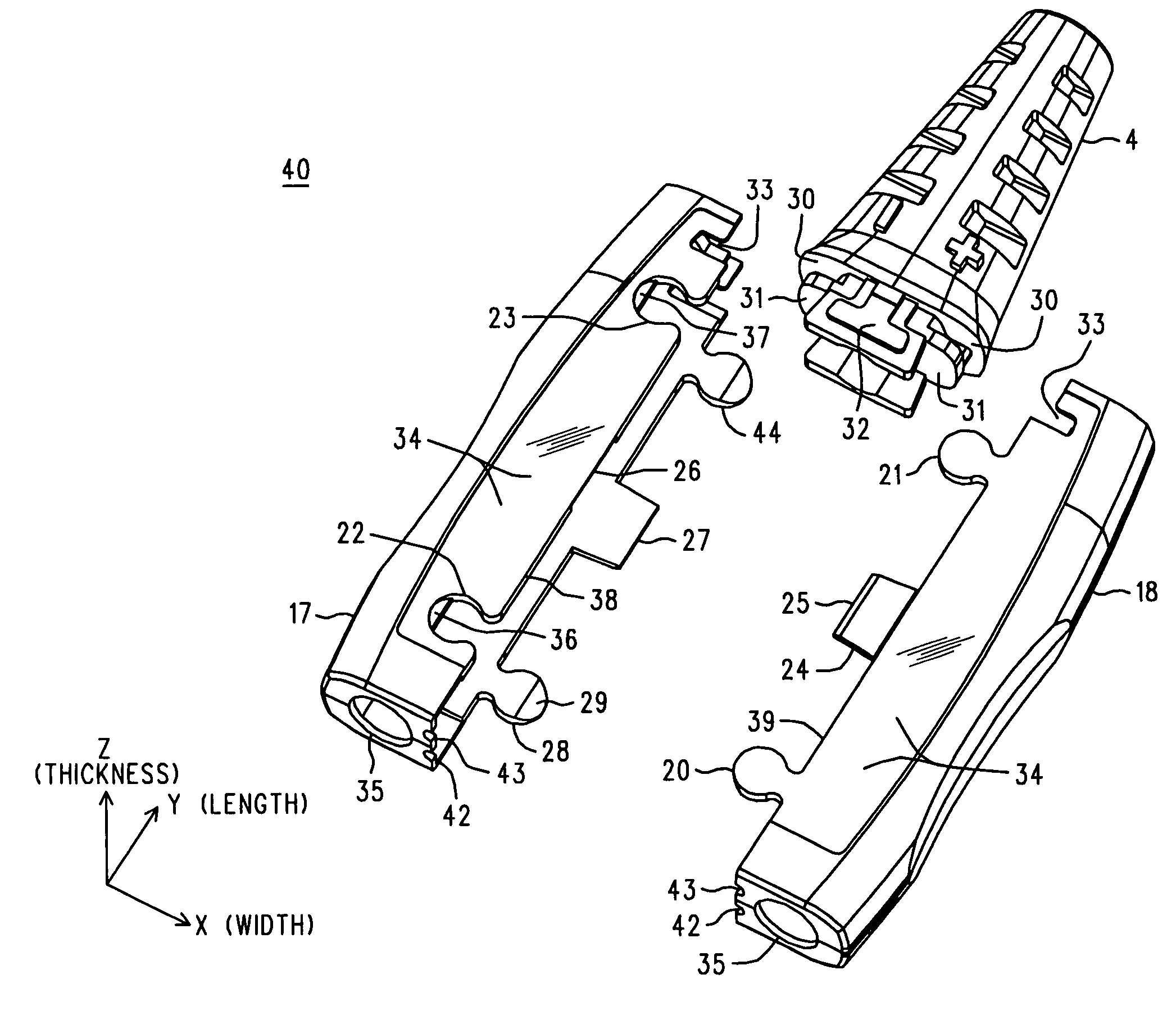
[0010]A housing for a thin active probe has two identical molded plastic parts (housing-halves) that when assembled form a cavity that encloses the chassis upon which is carried the active circuitry of the probe. The parts exhibit complementary self-symmetry about a longitudinal axis, such that when one is rotated about that axis it performs the mating functions needed to interlock with another part representing its un-rotated self. Interlocking is accomplished by circular tabs and sockets that interfere and prevent the parts from separating once the tabs are in the sockets. The circular tabs are joined to the balance of the housing-half that carries them by a narrow neck and can be sprung over the other housing-half to return to their natural position and fit into a circular socket in that other housing-half. A tapered edge or ramp portion on the underside of each circular tab allows it to automatically spring out of the way as the two parts are moved toward each other in a direction generally perpendicular to the longitudinal axis of the parts. The two housing-halves, once joined, can form an outer surface with useful a...

Problems solved by technology

Some high performance active probes dissipate a modest amount of power to accomplish their tasks; hence, they have to shed heat through surface area.
They can also be relatively expensive as small things go (say, on the order of a thousand dollars), and it is common for them to be returned to the factory for repair (vendors will sometimes offer loaners to the unfortunate owners during the interim .
It often happens that the probe simply won't fit into the available space, and circuit performance (or lack of space) precludes the use of an extender board.
The result is a nagging uncertainty in the quality of the measurement: what would the measurement have been if those leads were truly of minimum length?
We may still need to solder some short leads that extend from the probe to the point of electrical contact, simply because of the geometry of the parts involved: there is no way to clip or hook the probe tip to the circuit (e.g., grab onto a component leg), or even if there is, it won't work because the probe will not both stay hooked and lay flat against the board to occupy the available space between the boards.
Tiny threaded fasteners come to mind, but they consume space on the part, are fussy and add cost, not to mention aggravation (you heard that little screw hit the floor, but now it's GONE!).
And for aesthetic reasons, as well as to discourage (or at least make evident) tampering with parts that may be under warranty (“but we can't fix it if you tried to fix it first .

Method used


Image

  • Housing for a thin active probe
  • Housing for a thin active probe
  • Housing for a thin active probe

Examples


Embodiment Construction

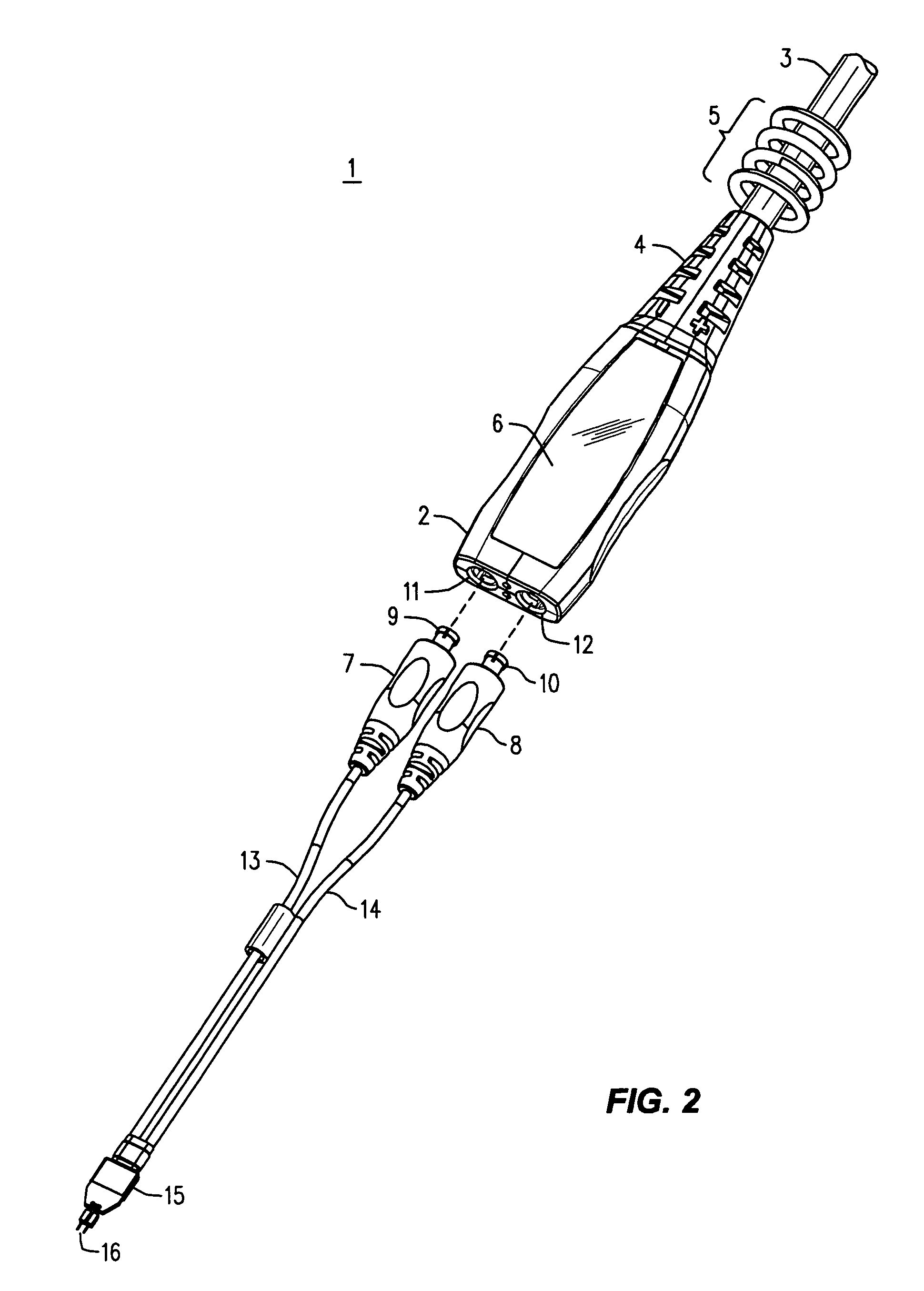
[0018]Refer now to FIG. 2, wherein is shown a partially exploded perspective view 1 of a thin active probe. The probe 2 has internal workings that are to be covered and protected by an outer housing that also anchors a strain relief (or boot) 4 for a cable 3. The cable leads to the instrument or item of test equipment (not shown) that the active probe is associated with. Since there may be several such probes in use at the same time, a collection 5 of removable colored elastic bands is provided to allow easy identification among the probes.

[0019]The body of the probe 2 has two relatively broad and flat recessed surfaces, the top-most one of which is visible (the other is parallel to it but on the underside) and that each receive an adhesive label (6 is one), such as metal foil embossed or printed with appropriate indicia.

[0020]At the front of the probe body 2 are two apertures 11 and 12. They allow access by plugs 9 and 10 to respective sockets within the probe body 2; those sockets...


PUM


Abstract

A housing for a thin active probe has two identical molded housing-halves that when assembled form a cavity that encloses the chassis upon which is carried the active circuitry of the probe. The parts exhibit complementary self-symmetry about a longitudinal axis, such that when one is rotated about that axis it performs the mating functions needed to interlock with another part representing its un-rotated self. Interlocking is accomplished by circular tabs and sockets that interfere and prevent the parts from separating once the tabs are in the sockets. The circular tabs are joined to the balance of the housing-half that carries them by a narrow neck and can be sprung over the other housing-half to return to their natural position and fit into a circular socket in that other housing-half. A tapered edge or ramp portion on the underside of each circular tab allows it to automatically spring out of the way as the two parts are moved toward each other in a direction generally perpendicular to the longitudinal axis of the parts. Each circular socket contains a stop that prevent its tab from completely passing through the socket. Each housing-half has a straight tab between its circular tabs that enter an interior recess on the other housing-half to support its circular sockets as they receive their tabs. Each housing-half contains in a front surface an entire aperture for a detachable probe lead, and each contains in a rear surface at least one half-aperture that, when the two housing-halves are joined, forms a larger aperture whose perimeter engages a corresponding groove in a strain relief for a cable. The exterior surface of the mated housing-halves has, on each side through which runs the line of the mating edges, a flat shallow recess. The interlocking circular tabs and sockets are located within the extent of this shallow recess, which can receive an adhesive label that may conceal and stiffen the interlocking circular tabs and sockets.

Description

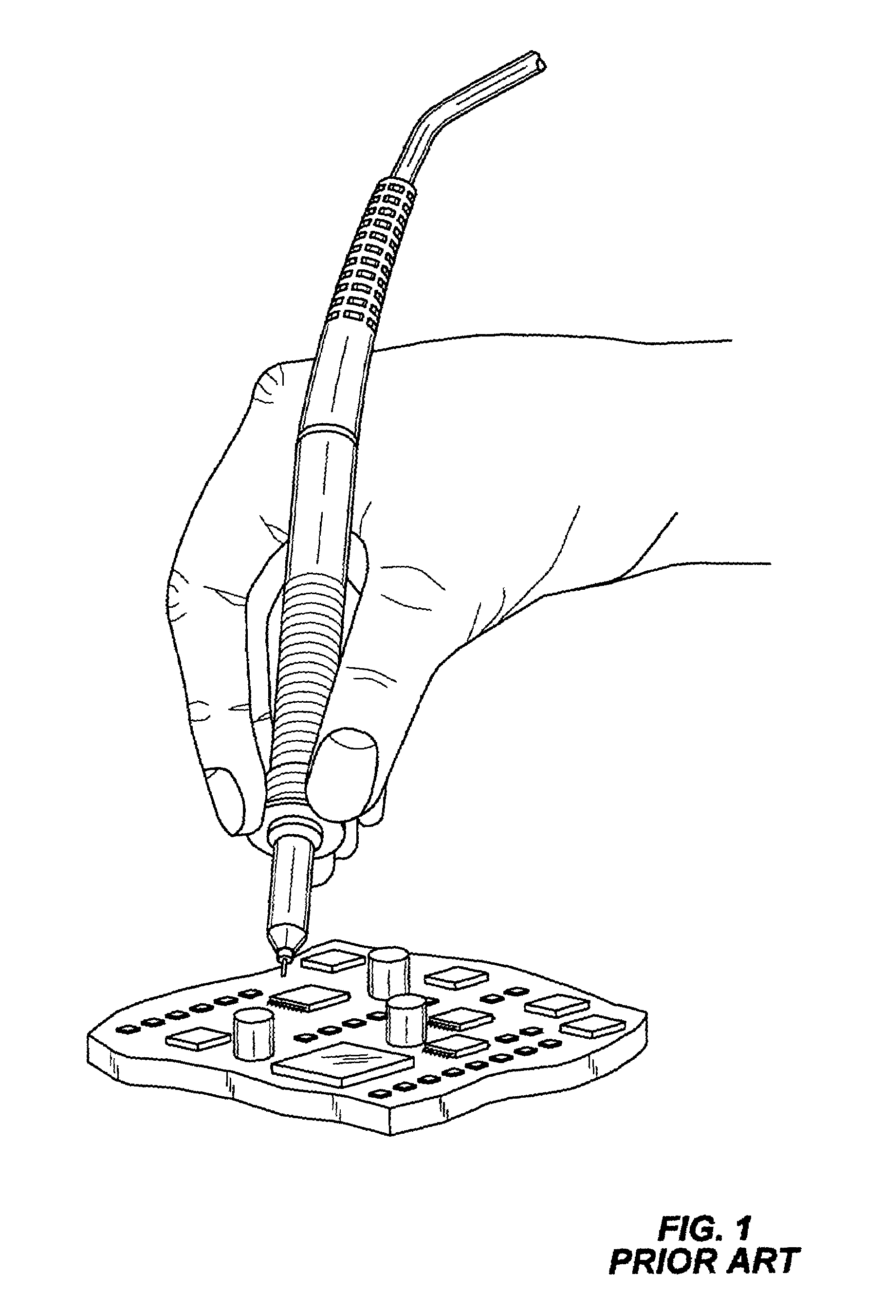
BACKGROUND OF THE INVENTION [0001]Various types of electronic test equipment use hand held probes to establish an electrical connection between the test equipment and a work piece. Sometimes these probes are passive; that is, they contain no active elements, such as FETs or bipolar transistors. Absent some special consideration, passive probes can generally be small, and their size is set by what is comfortable to handle, on the one hand, and functional in terms of electrical performance, on the other. (There are exceptions, of course, such as the foot long 30 KV high voltage probe for a voltmeter.) Active probes are necessitated by particular electrical considerations, generally involving high frequency operation and impedance. So, for example, an oscilloscope probe that is expected to work into the several gigahertz region needs to prevent the length of cable connecting the probe to the test equipment from being seen by the work circuit and must also exercise rigorous control over...

Claims


Application Information

Patent Timeline
IPC IPC(8): H01R13/514G01R1/067
CPCH01R13/5825G01R1/06788G01R1/06766G01R1/06772H01R13/504
Inventor DANCEL, MICHAELCANNON, JAMES E.
Owner AGILENT TECH INC
Learn More