Nonvolatile semiconductor memory
a semiconductor memory and non-volatile technology, applied in static storage, digital storage, instruments, etc., can solve the problems of potential generating circuits operating continuously, increasing production costs, and deteriorating reading margins, so as to reduce production costs and reduce unstable factors
- Summary
- Abstract
- Description
- Claims
- Application Information
AI Technical Summary
Benefits of technology
Problems solved by technology
Method used
Image
Examples
embodiment 1
(Embodiment 1)
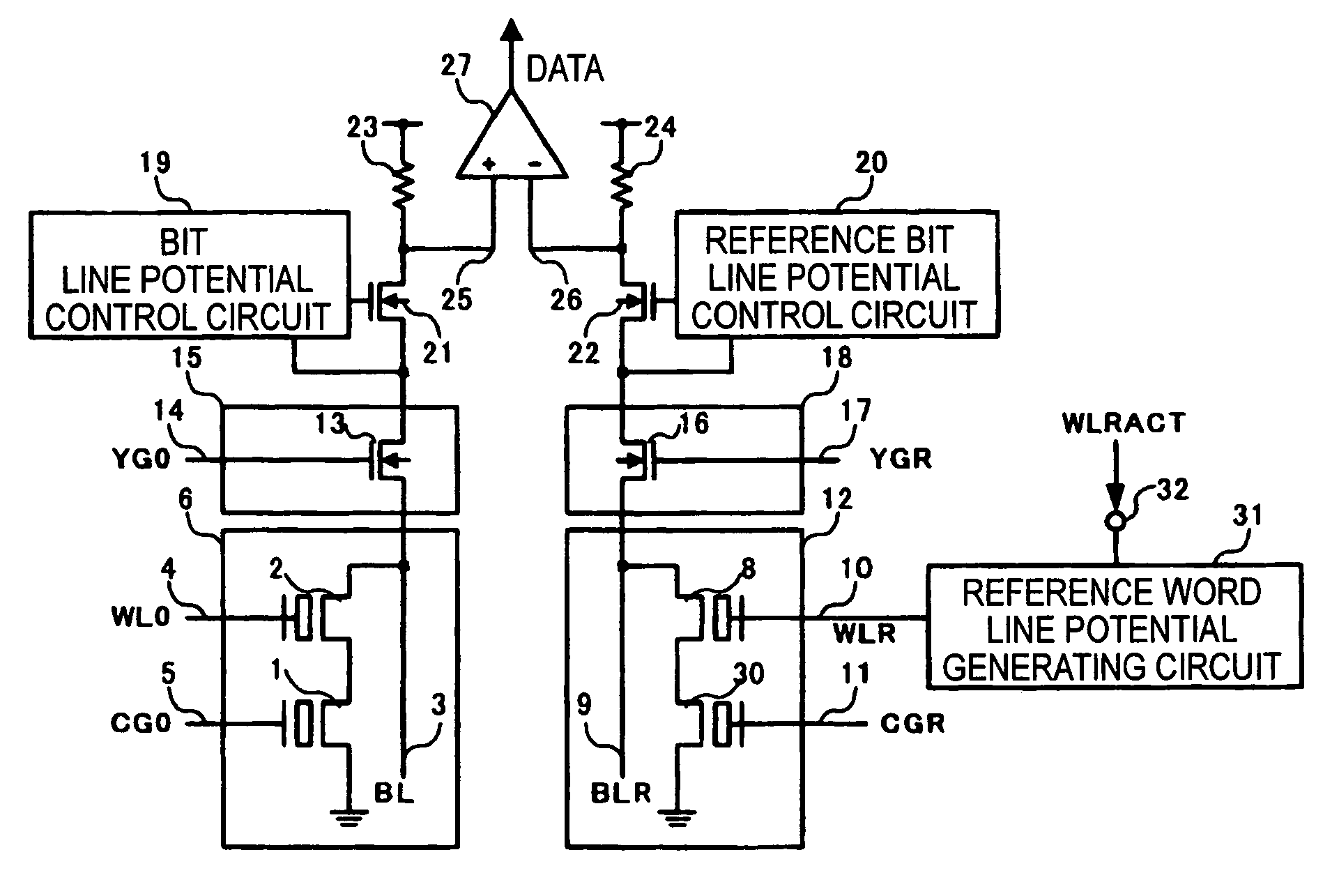
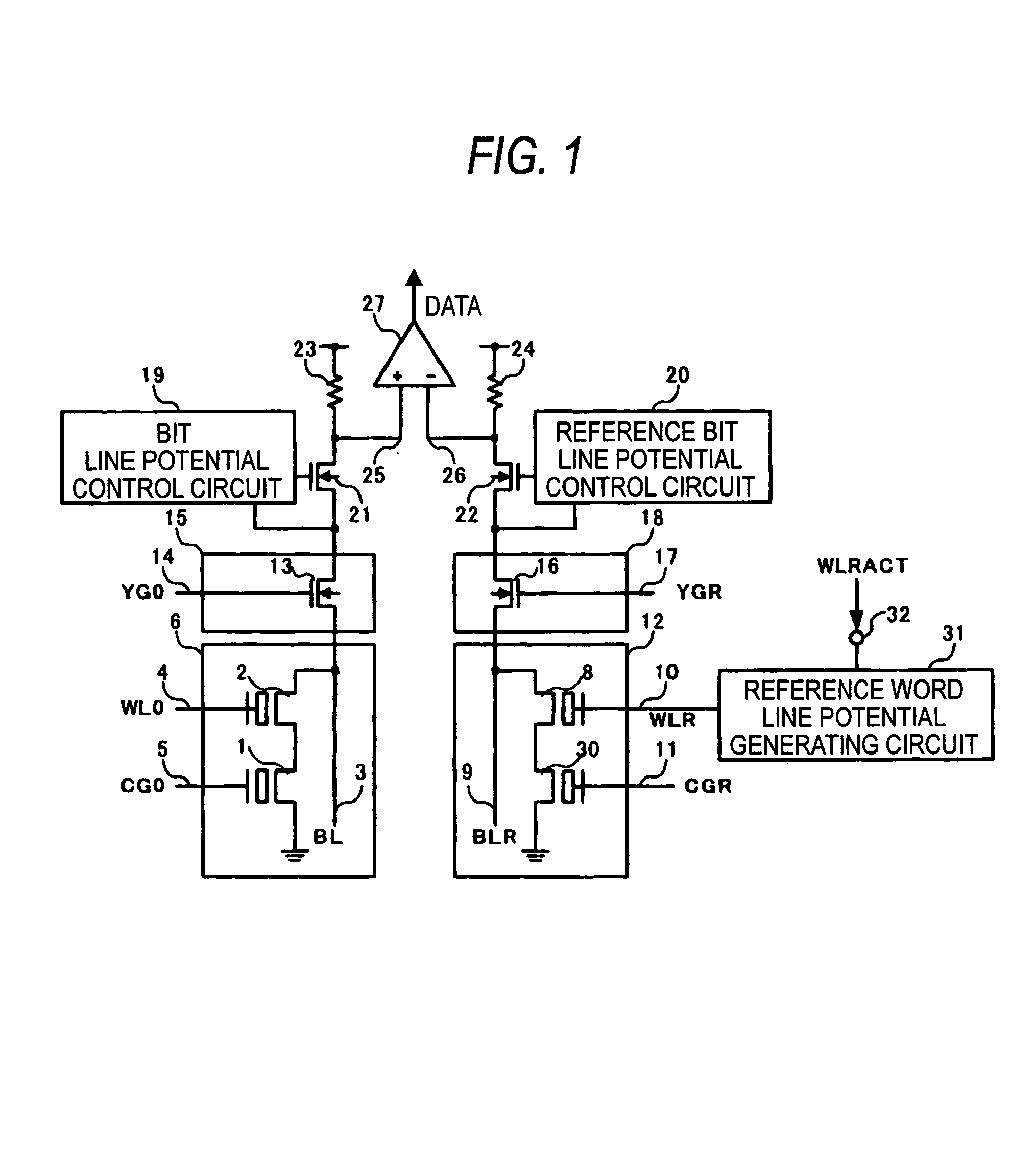
[0074]FIG. 1 is a block diagram showing an overall configuration of a nonvolatile semiconductor device according to an embodiment 1 of the present invention. In FIG. 1, 1 is the memory cell transistor, 2 the memory cell selecting transistor, 3 the bit line, 4 the word line, 5 the memory cell transistor control gate line, 6 the memory cell array composed of nonvolatile memory cells, 8 the reference cell selecting transistor, 9 the reference bit line, 10 the reference word line, 11 the reference cell transistor control gate line, and 12 the reference cell array composed of reference cells.
[0075]Also, 13 is the column gate, 14 the column gate selecting line, 15 the column decoder, 16 the reference column gate, 17 the reference column gate selecting line, 18 the reference column decoder, 19 the bit line potential control circuit, 20 the reference bit line potential control circuit, 21 the bit line potential control transistor, 22 the reference bit line potential control tr...
embodiment 2
(Embodiment 2)
[0096]FIG. 5 and FIG. 6 are a circuit diagram showing a configuration of the reference word line potential generating circuit of the nonvolatile semiconductor memory according to an embodiment 2 of the present invention respectively. Also, FIG. 7 is a waveform diagram explaining an operation of the present embodiment. An overall configuration of the nonvolatile semiconductor memory is similar to that in FIG. 1 explained in the embodiment 1.
[0097]In FIG. 5, 60 is a reference word line driver, 61, 62 potential generating means, 63 an output node from the potential generating means 61, 62, 64 a signal READ activated in a reading operation mode period, 65 a signal ACT1 for activating the word line potential generating means 61, 66 a signal ACT2 for activating the word line potential generating means 62, and 67 a delayed pulse generating means.
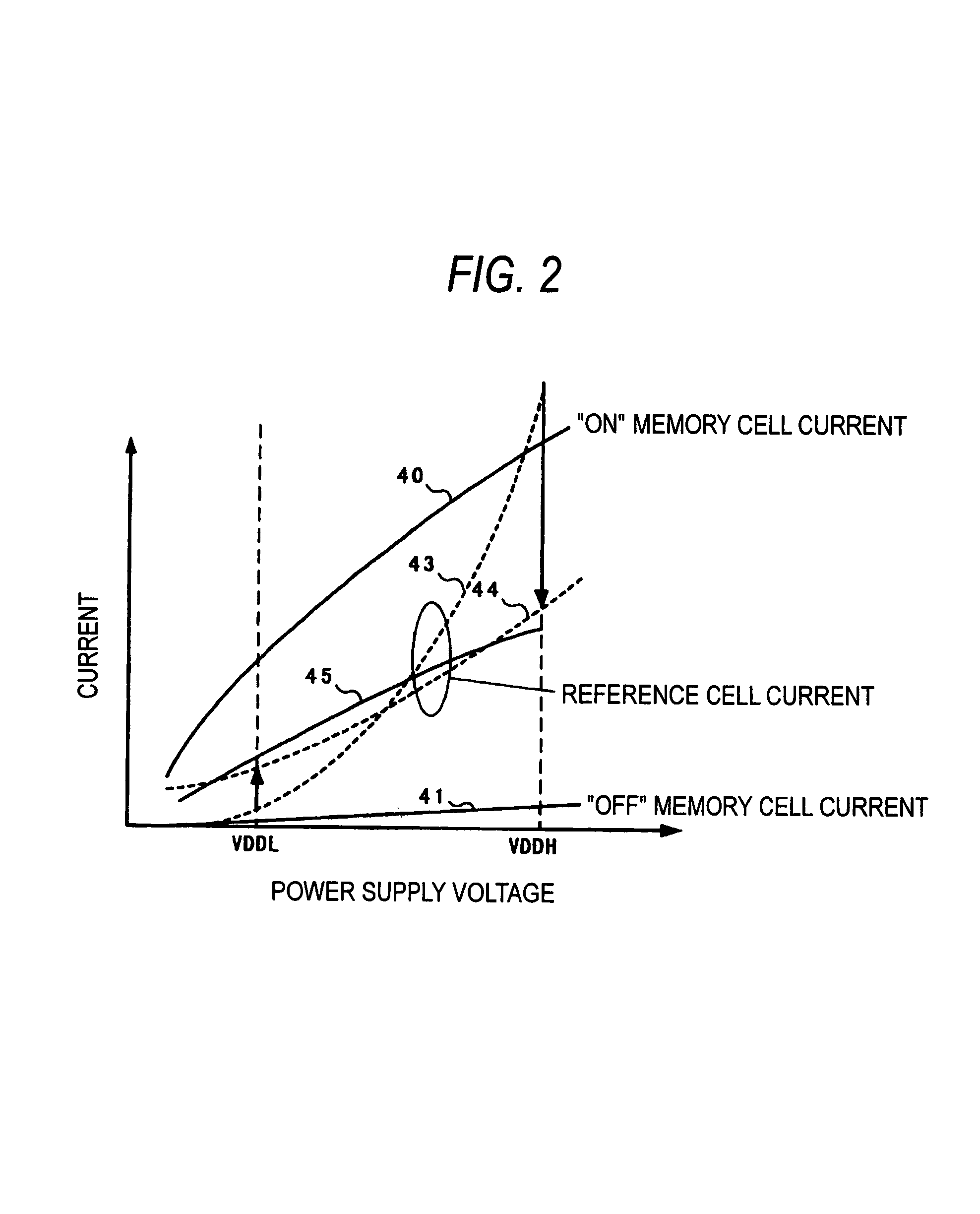
[0098]In the nonvolatile semiconductor memory constructed as above, the signal READ is activated in the reading mode. Then, when WLR...
embodiment 3
(Embodiment 3)
[0108]FIG. 8 is a circuit diagram showing a configuration of the reference word line potential generating circuit of a nonvolatile semiconductor memory according to an embodiment 3 of the present invention. FIG. 9 is a waveform diagram explaining an operation of the present embodiment. An overall configuration of the nonvolatile semiconductor memory is similar to that in FIG. 1 explained in the embodiment 1.
[0109]In FIG. 8, 60 to 66 are constituent elements of the reference word line potential generating circuit similar to those shown in FIG. 5, and 70 is a smoothing capacitor that makes the potential of the output node 63 smooth when the signal WLRACT is activated to supply the current.
[0110]Here, the current supply capability and the consumption current of the potential generating means 62 are set smaller than those of the potential generating means 61. The potential generating means 61 is activated only by WLRACT of the reference cell selecting signal 32, while the ...
PUM
 Abstract
Description
Claims
Application Information
 - R&D
- Intellectual Property
- Life Sciences
- Materials
- Tech Scout
- Unparalleled Data Quality
- Higher Quality Content
- 60% Fewer Hallucinations
Browse by: Latest US Patents, China's latest patents, Technical Efficacy Thesaurus, Application Domain, Technology Topic, Popular Technical Reports.
© 2025 PatSnap. All rights reserved.Legal|Privacy policy|Modern Slavery Act Transparency Statement|Sitemap|About US| Contact US: help@patsnap.com


