Process for extracting ethane and heavier hydrocarbons from LNG

a technology of ethane and hydrocarbons, which is applied in the direction of container discharging methods, lighting and heating apparatus, and container filling under pressure, etc. it can solve the problems of not fully utilizing the process, adding to the capital cost and fuel consumption of the process, and reducing the extraction efficiency of ngl products

Active Publication Date: 2007-01-23
PI TECH ASSOC INC
View PDF15 Cites 57 Cited by
  • Summary
  • Abstract
  • Description
  • Claims
  • Application Information

AI Technical Summary

Benefits of technology

[0014]Development and optimization of new processing technology is the “cornerstone” for the continued growth and expansion of the LNG industry. The industry needs a more efficient process to extract and remove ethane and heavier hydrocarbons (NGL) from LNG. The disclosed system(s) and method(s) provide industry with a step forward in improving technology for efficiently extracting NGL products from LNG.
[0015]The process disclosed reflects a significant improvement over prior patents and existing technology for the extraction of ethane and heavier hydrocarbons from LNG. The process of the disclosed embodiment(s) will reduce capital costs and improve fuel efficiency when compared to current practice from existing patented technology. The process of the embodiment(s) maximizes the utilization of the beneficial cryogenic thermal properties of the LNG using a unique arrangement of heat exchange equipment and processing parameters that essentially eliminates (or greatly reduces) the need for gas compression equipment required in other patented technology of this field. Elimination or minimization of gas compression equipment minimizes the capital cost and minimizes fuel consumption or electrical power consumption, which reduces operating expenses. Use of our process in a facility designed to handle 1,000 MMscfd of send-out gas will require only 150 to 550 horsepower of gas compression when processing LNG rich in ethane and heavier hydrocarbons. For leaner LNG compositions our gas compression horsepower increases, but still remains less than 1,000 horsepower for a 1,000 MMscfd send-out capacity which compares to the 5,000 to 7,000 horsepower required by the leading competitor process disclosed in U.S. Pat. No. 6,604,380 referenced herein. Translating this comparison into economic terms, our process would result in a current-day capital cost savings ranging between $4.5 to $5.5 million and our fuel consumption savings would range between 335,000 to 480,000 MMBtus per annum based on a throughput capacity of 1,000 MMscfd. At current natural gas prices (assume $5.00 / MMBtu average), our fuel expense savings would range between $1.7 to $2.4 million per annum.
[0026]A small cryogenic compressor is required to compress the Tail Gas that is not re-liquefied by the cross exchange pre-heat step to gas pipeline send-out pressure. If the overall facility has a need for fuel gas, the Tail Gas can be used as a source of fuel, which reduces the amount of gas requiring compression. The volume of Tail Gas for our process is very small ranging between 0 to 5 mole % of the total gas throughput capacity when the Rich LNG feed composition contains more than 8 mole % C2+. Lower C2+ content in the Rich LNG feed causes the Tail Gas fraction in our process to increase. For feeds containing only 2.5 mole % C2+, Tail Gas for our process would be as high as 7 to 10 mole % of the total gas throughput capacity.

Problems solved by technology

This practice does not capture and fully utilize the benefits of the cryogenic conditions available from the LNG.
Compression and heating adds to the capital costs and fuel consumption of the process.
Additional cooling and compression are required to make a liquid NGL product that adds to the capital cost and fuel consumption for making the final NGL product.
This compressor and its associated fuel consumption add to the capital cost and operating expense for the facility.

Method used


Image

  • Process for extracting ethane and heavier hydrocarbons from LNG
  • Process for extracting ethane and heavier hydrocarbons from LNG

Examples


example

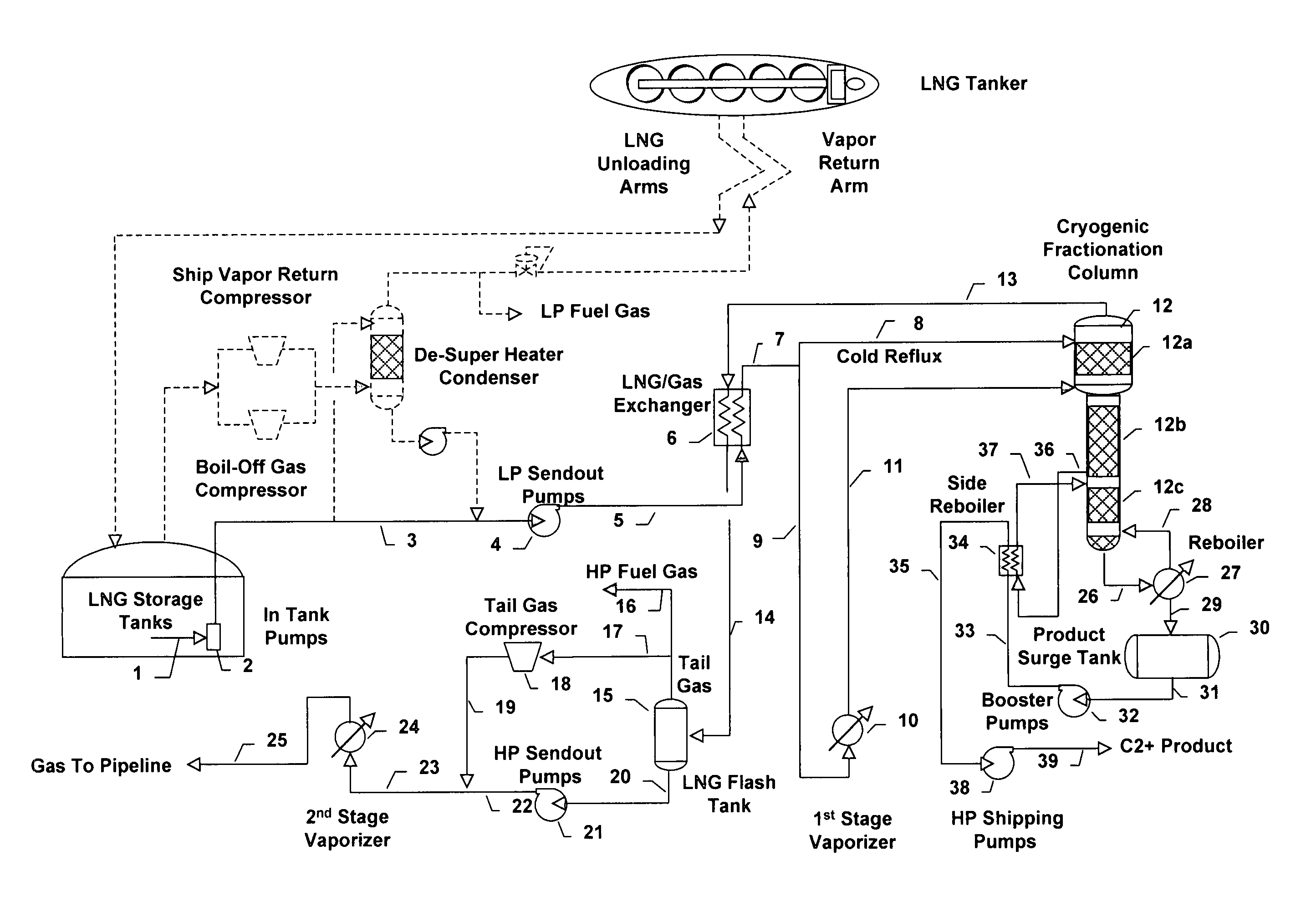
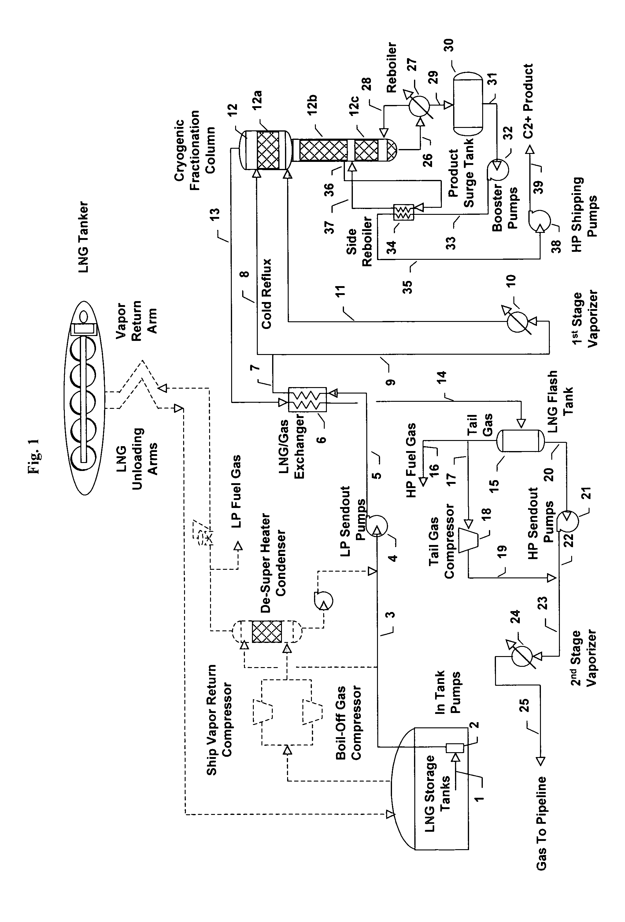
[0054]One process embodiment as illustrated in FIG. 1 was modeled using a commercially available process simulation program called HYSYS (available from AspenTech of Calgary, Alberta Canada). HYSYS is commonly used by the oil and natural gas industry to evaluate and design process systems of this type. A wide range of LNG feed compositions were evaluated using the HYSYS model of our process. The HYSYS model calculation results for our process are summarized in Tables 1 and 2 below for one of the LNG feed compositions evaluated. The Example results given in Tables 1 and 2 are intended to illustrate performance of our process operating in the “High Ethane Recovery” mode for a typical LNG feed composition. Stream numbering in Tables 1 and 2 coincide with those illustrated in FIG. 1. Any person trained and skilled in the technical art of process engineering, particularly one having the benefit of these disclosed embodiments, will recognize the possibility for variations to the process c...


PUM


Abstract

A process for the extraction and recovery of ethane and heavier hydrocarbons (C2+) from LNG. The process covered by this patent maximizes the utilization of the beneficial cryogenic thermal properties of the LNG to extract and recover C2+ form the LNG using a unique arrangement of heat exchange equipment, a cryogenic fractionation column and processing parameters that essentially eliminates (or greatly reduces) the need for gas compression equipment minimizing capital cost, fuel consumption and electrical power requirements.This invention may be used for one or more of the following purposes:to condition LNG so that send-out gas delivered from an LNG receiving and regasification terminal meets commercial natural gas quality specifications;to condition LNG to make Lean LNG that meets fuel quality specifications and standards required by LNG powered vehicles and other LNG fueled equipment;to condition LNG to make Lean LNG so that it can be used to make CNG meeting specifications and standards for commercial CNG fuel;to recover ethane, propane and / or other hydrocarbons heavier then methane from LNG for revenue enhancement, profit or other commercial reasons.

Description

CROSS-REFERENCE TO RELATED APPLICATIONS[0001]This application claims the benefit of U.S. provisional application No. 60 / 605,182 filed Aug. 27, 2004.FEDERALLY SPONSORED RESEARCH OR DEVELOPMENT[0002]Not applicable.Reference to Listing, Tables or Compact Disk Appendix [0003]Not applicable.BACKGROUND OF THE INVENTION[0004]Natural gas is a clean-burning hydrocarbon fuel that produces less “greenhouse gases” upon total combustion than that produced from combustion of heavier hydrocarbons such as gasoline, diesel, fuel oil and coal. As a result, natural gas has been identified as an “environmentally friendly” fuel. In recent years, demand for natural gas has been outpacing wellhead supplies that are available for direct connection and delivery into the gas pipeline transport and distribution systems throughout the world, and particularly so within the United States and Europe. As a result, natural gas marketers, pipeline transporters, distributors and power utilities are turning to Liquefi...

Claims


Application Information

Patent Timeline
Patent Type & Authority Patents(United States)
IPC IPC(8): F25J3/00
CPCF17C5/06F25J3/0214F25J3/0233F25J3/0238F17C9/02F25J2290/62F17C2221/033F17C2223/0161F17C2223/033F17C2223/047F17C2225/0123F17C2225/035F17C2227/0135F17C2227/0178F17C2227/0185F17C2227/0318F17C2227/033F17C2227/0332F17C2227/0393F17C2250/0456F17C2265/015F17C2265/03F17C2265/034F17C2265/037F17C2265/05F17C2270/0105F17C2270/0136F25J2200/02F25J2200/50F25J2200/70F25J2205/02F25J2220/62F25J2230/08F25J2230/60F25J2235/60F25J2245/90F25J2260/30F25J2260/60F25J2270/02F25J3/0242F25J2280/02F25J2210/06F25J2215/02F25J2205/90
Inventor WINNINGHAM, HORACE GARY
Owner PI TECH ASSOC INC
Why Eureka
Try Eureka