
Process for forming a ziegler-natta catalyst system having a controlled morphology

a technology of zieglernatta and catalyst, which is applied in the direction of catalyst activation/preparation, physical/chemical process catalyst, chemical/physical process, etc., can solve the problems of sacrificing the original activity and stereospecificity of the catalyst, and morphological optimization typically

Inactive Publication Date: 2007-01-30
FINA TECH
View PDF22 Cites 27 Cited by
  • Summary
  • Abstract
  • Description
  • Claims
  • Application Information

AI Technical Summary

Problems solved by technology

Unfortunately, modification of conventional supported catalysts to optimize morphology typically sacrifices the original activity and stereospecificity of the catalysts.

Method used


Image

  • Process for forming a ziegler-natta catalyst system having a controlled morphology
  • Process for forming a ziegler-natta catalyst system having a controlled morphology
  • Process for forming a ziegler-natta catalyst system having a controlled morphology

Examples


example 1

[0030]The pre-catalyst component sample was prepared in accordance with the present invention and then used to prepare a polypropylene sample. Some of the compounds required to prepare the catalyst component sample, i.e., 2-ethylhexanol, tri-n-butylphosphate (BP), di-n-butylphthalate (DnBP), TiCl4, and 1,2-dichloroethane (DCE) were purchased from Aldrich Chemical Company and were used as received. A butylethylmagnesium (BEM) solution containing 24.7 wt. % BEM and 0.47 wt. % TEAL in heptane was purchased from Akzo Nobel and used as received. Toluene and hexane were purchased from Aldrich and dried over activated alumina in preparation for this experiment.

[0031]The support for the pre-catalyst sample was prepared by first charging a round bottom flask with 13.3 g (24.6 mmols) of the BEM solution and 25 mL of toluene. A solution of 2-ethylhexanol in toluene (23 ml of 2.2 M solution) was added over one hour with stirring. The resulting solution was allowed to stir for an additional one ...

example 2

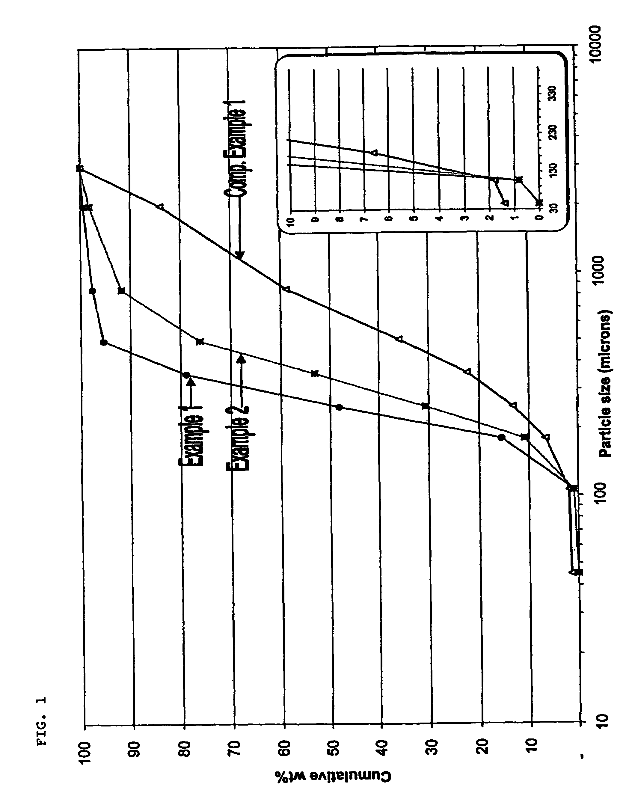
[0036]The procedure of Example 1 was followed except that 1.5 equivalent of BP instead of 1.0 equivalent of BP was used to prepare the catalyst support, thereby forming a pre-catalyst sample from which a PP sample was formed. The PP sample was prepared using 0.09 mol % H2. The resultant fluff particle size was larger (d50=340 μm) than that found from Example 1 (d50=275 μm).

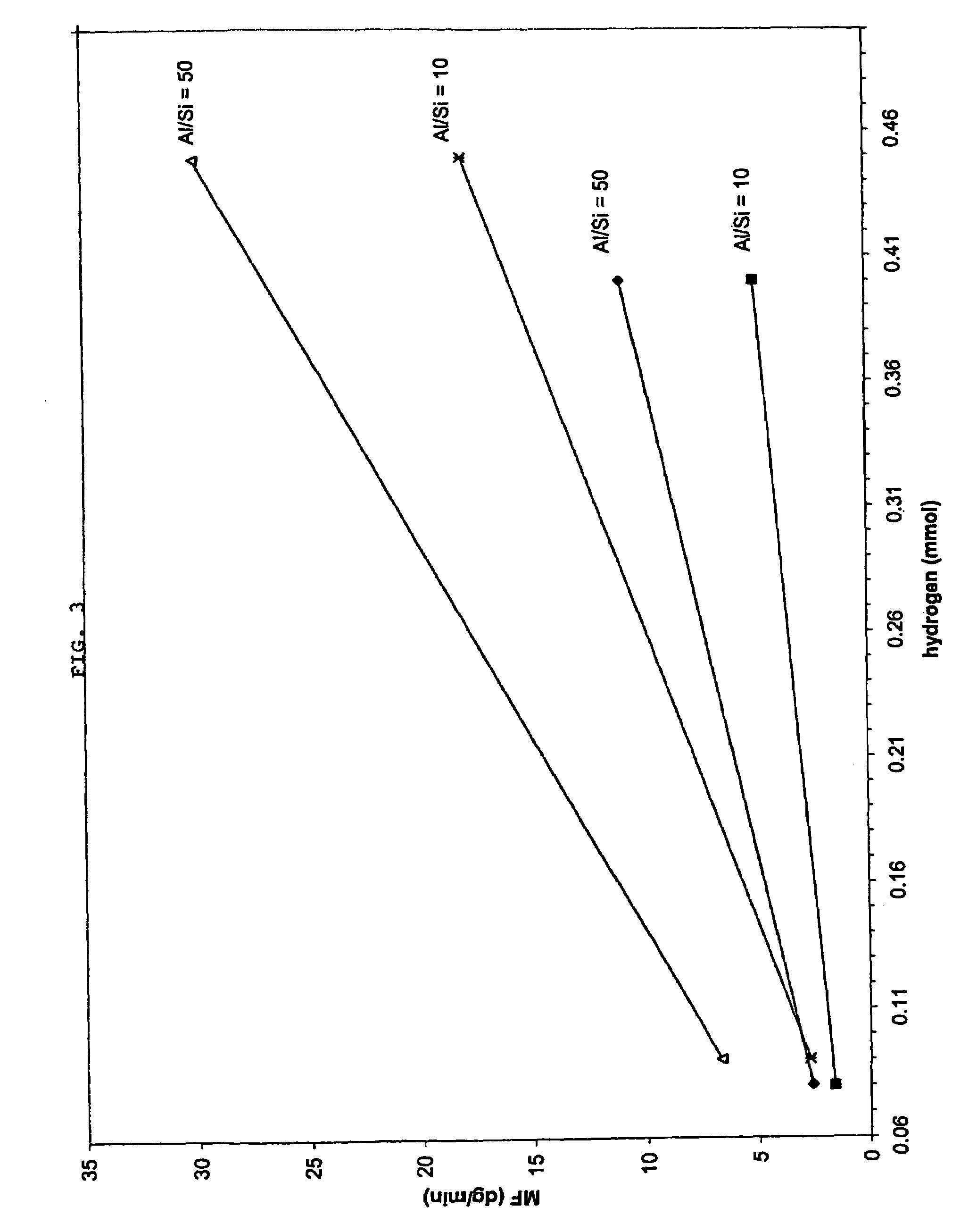
[0037]As shown in Table 1, the melt flow rate of the PP decreased as the amount of BP was increased from 1.0 equivalent to 1.5 equivalent. On the other hand, the xylene solubles content decreased, the crystallinity increased, and the bulk density increased as the amount of BP was increased from 1.0 equivalent to 1.5 equivalent, thus achieving improved polymer properties.

example 3

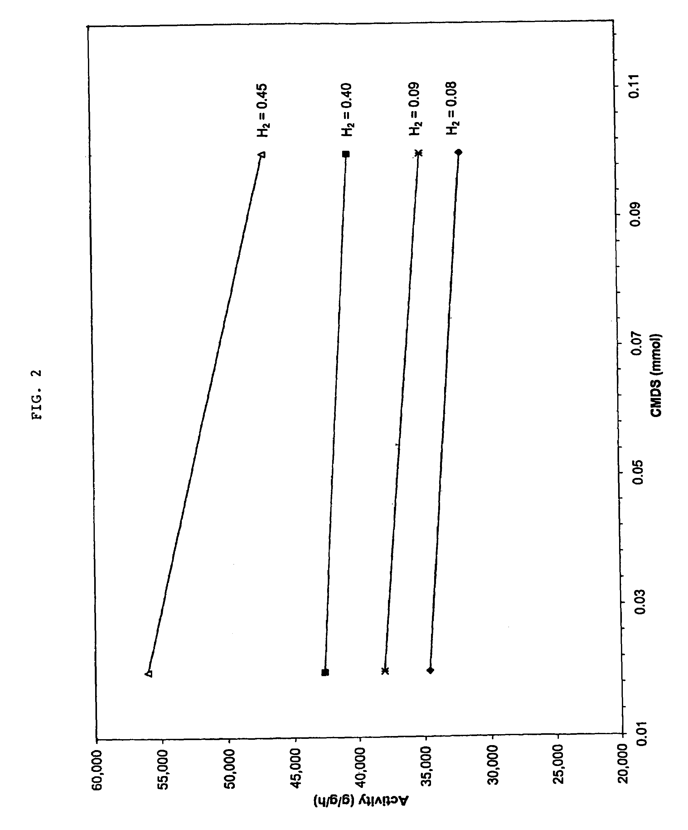
[0038]The procedure of Example 1 was followed except that 1.5 equivalent of BP instead of 1.0 equivalent of BP was used to prepare a pre-catalyst sample, and a PP sample was prepared using 0.45 mol % H2 instead of 0.09 mol % H2.


PUM

PropertyMeasurementUnit
temperatureaaaaaaaaaa

Abstract

A pre-catalyst is formed by reacting butylethylmagnesium with an alcohol to form a magnesium alkoxide compound, followed by contacting the magnesium alkoxide compound with a phosphorous compound to form a magnesium alkoxide phosphorous compound mixture. The magnesium alkoxide phosphorous compound mixture is subsequently reacted with TiCl4 to form a MgCl2 support. The MgCl2 support is then contacted with an internal donor while being heated to form a first catalyst slurry, which is then contacted with TiCl4 while being heated to form a second catalyst slurry. The second catalyst slurry is next contacted with TiCl4 while being heated to form a third catalyst slurry, which is washed and dried, resulting in a highly active pre-catalyst with controlled morphology. The pre-catalyst may be combined with one or more co-catalysts and optionally one or more external electron donors to form an active catalyst system, which may be used for the polymerization of olefins.

Description

CROSS-REFERENCE TO RELATED APPLICATIONS[0001]This application is a divisional of application Ser. No. 10 / 447,914, filed May 29, 2003, now U.S. Pat. No. 6,767,875.STATEMENT REGARDING FEDERALLY SPONSORED RESEARCH OR DEVELOPMENT[0002]Not applicable.REFERENCE TO A MICROFICHE APPENDIX[0003]Not applicable.FIELD OF THE INVENTION[0004]This invention generally relates to forming a Ziegler-Natta catalyst system for use in the polymerization of alpha-olefins, for example polypropylene. More specifically, the invention relates to forming a Ziegler-Natta pre-catalyst component by reacting a phosphorous compound with a magnesium alkoxide to facilitate precipitation of a magnesium chloride catalyst support wherein the magnesium alkoxide component is formed by reacting butylethylmagnesium with an alcohol.BACKGROUND OF THE INVENTION[0005]Olefins, also called alkenes, are unsaturated hydrocarbons whose molecules contain one or more pairs of carbon atoms linked together by a double bond. When subjecte...

Claims


Application Information

Patent Timeline
Patent Type & Authority Patents(United States)
IPC IPC(8): B01J31/00C08F10/00C08F110/02C08F110/06C09K8/62C09K8/68
CPCC08F10/00C08F110/06C08F4/6546C08F4/6541C08F4/651C08F110/02C08F2500/12C08F2500/18C08F2500/04C08F2500/24
Inventor THORMAN, JOSEPH LYNDON
Owner FINA TECH
Learn More