DC to DC converter with high frequency zigzag transformer

a converter and transformer technology, applied in the direction of dc-dc conversion, power conversion systems, instruments, etc., can solve the problems of high switching frequency of hard switching converters beyond 1 mhz, current imbalance, and technical problems of these conventional converters, so as to simplify current control, reduce current ripple, and improve transient response

Active Publication Date: 2007-01-30
LITE ON TECH CORP
View PDF5 Cites 67 Cited by
  • Summary
  • Abstract
  • Description
  • Claims
  • Application Information

AI Technical Summary

Benefits of technology

[0008]In view of the foregoing problems, a DC to DC converter with a high frequency zigzag transformer is provided to substantially eliminate the problems of the conventional topology. The disclosed DC to DC converter with a high frequency zigzag transformer is capable of reducing current ripple, simplifying current control, and achieving better transient response. Current ripples are reduced on all switching devices and passive components by adjusting the operating point near boundary conditions. So conduction losses are minimized at the operating points near boundary conditions. Current sharing control is not necessary and transient response is faster because all phase currents flow equally through the transformer windings. Phase-shifted PWM switching signals offer balanced voltages in the transformer windings.
[0011]According to the principle of the invention, the disclosed DC to DC converter has the advantage of not requiring current-sharing technique.
[0012]According to the principle of the invention, the disclosed DC to DC converter has another advantage of having no current ripples on passive and switching components.
[0013]According to the principle of the invention, the disclosed DC to DC converter has another advantage of lower conduction loss.
[0014]According to the principle of the invention, the disclosed DC to DC converter has another advantage of fast transient response even with lower switching frequency.

Problems solved by technology

However, such a high switching frequency of hard switching converter beyond 1 MHz is not available nowadays.
Current imbalance may occur due to component tolerances and / or parameter variations.
However, there are some technical problems in these conventional converters.
For example, they require three currents sensed for current sharing purposes, and thus suffer from higher ripple current on semiconductor devices.
Furthermore, the conventional converter requires many magnetic cores.

Method used


Image

  • DC to DC converter with high frequency zigzag transformer
  • DC to DC converter with high frequency zigzag transformer
  • DC to DC converter with high frequency zigzag transformer

Examples


Embodiment Construction

[0035]The invention will become more fully understood from the detailed description given in the illustration below only, and is thus not limitative of the present invention. Reference will now be made in detail to the preferred embodiments of the present invention, examples of which are illustrated in the accompanying drawings.

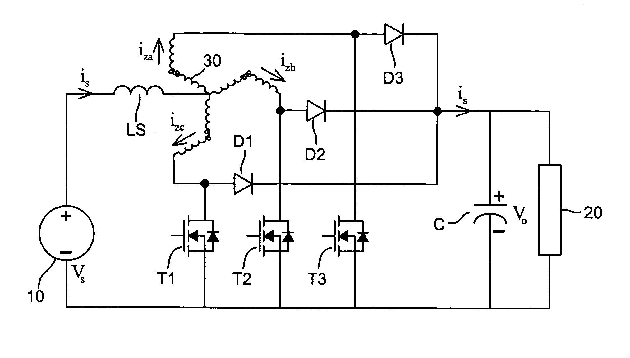
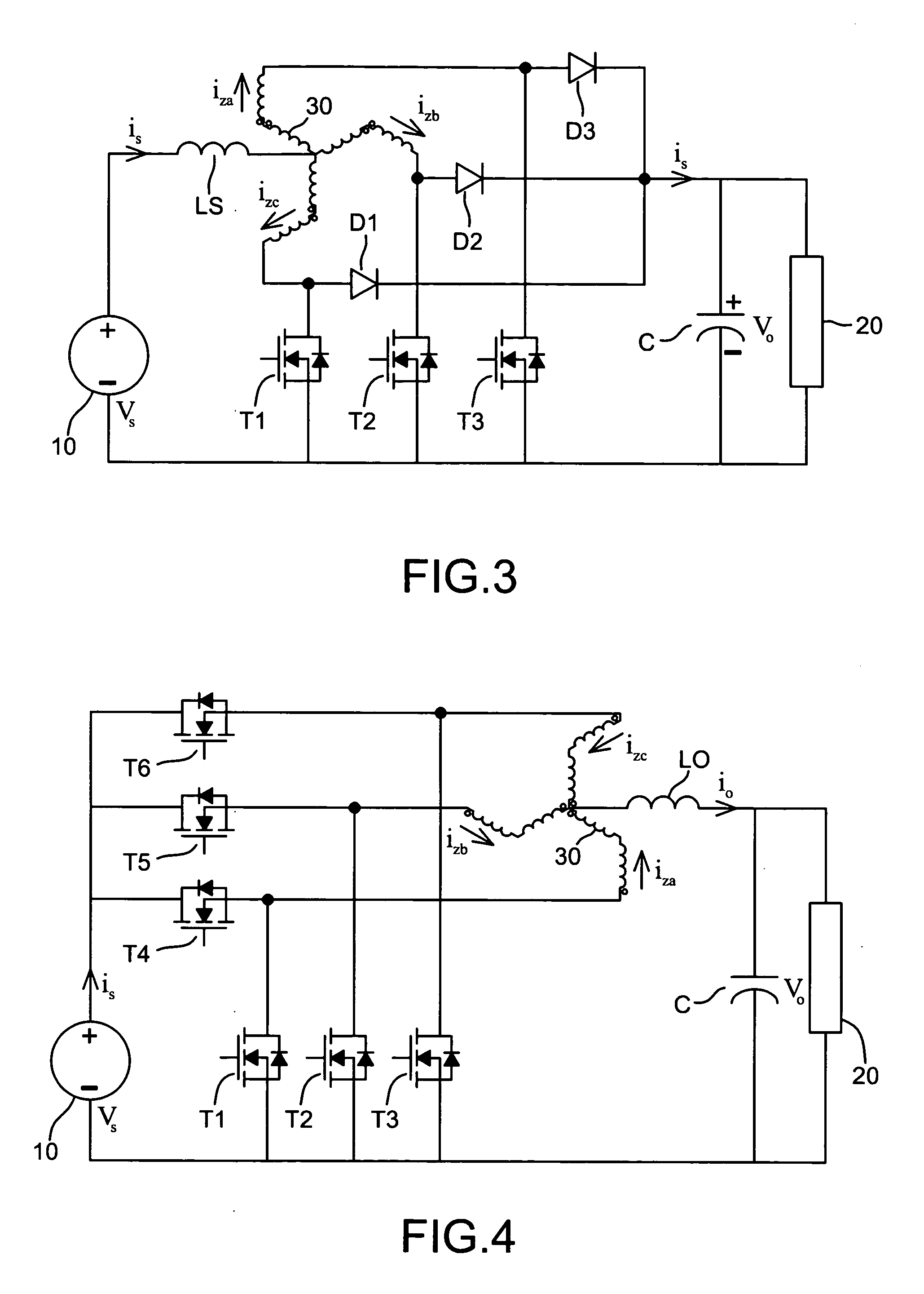
[0036]Refer to FIG. 3, which illustrates the circuit diagram of a boost converter in accordance with the invention. The boost converter, which boosts the power source 10 to the load 20, is composed of a transformer 30, an input inductor LS, a first diode D1, a second diode D2, a third diode D3, a first transistor T1, a second transistor T2 and a third transistor T3. A capacitor C is connected in parallel with the load 20.

[0037]The transformer 30 is a kind of autotransformer that does not provide isolation. For example, a zigzag transformer having three terminals may be adopted as the transformer 30. The core material of the transformer 30 should be ferrite wi...


PUM


Abstract

A DC to DC converter including a zigzag transformer. The transformer operates at high frequency with integrated magnetics and does not provide isolation. The multiphase converter has gate inputs with PWM signals appropriately phase-shifted depending on the number of phases to make balanced phase voltages across the transformer windings. The switching frequency of the converter is relatively low but fast transient response can be achieved by adding an integrated zigzag transformer.

Description

BACKGROUND OF THE INVENTION[0001]1. Field of Invention[0002]The invention relates to a DC to DC converter, and particularly to a DC to DC converter with a high frequency zigzag transformer.[0003]2. Related Art[0004]Dc-dc converters are widely used for battery-powered electronic equipment, renewable energy systems, and voltage regulator modules (VRM) to produce a regulated voltage or current derived from an unregulated power supply. Most converters require a higher switching frequency to improve the transient response and to reduce the size of passive components. However, such a high switching frequency of hard switching converter beyond 1 MHz is not available nowadays. Therefore, multiple operations with an interleaved switching on-off control are preferable for low voltage, high current converters. The paralleled interleaving operation of the switching converter is gaining popularity because it is more efficient. The I2R conduction power loss associated with power components of eac...

Claims


Application Information

Patent Timeline
Patent Type & Authority Patents(United States)
IPC IPC(8): G05F1/40H02M1/14H02M3/156H02M3/158
CPCH02M1/14H02M3/1584H02M3/156
Inventor KIM, SANGSUN
Owner LITE ON TECH CORP
Why Eureka
Try Eureka