
Apparatus and method for generating 3D images

a technology applied in the field of approximation and image generation, can solve the problems of not being able to undo or reverse operations, bending the tube within the framework of tools, and often no editing features, etc., and achieves the effect of fast approximation method and precise evaluation

Inactive Publication Date: 2007-02-06
FIGMENT3D ENTERPRISES
View PDF4 Cites 37 Cited by
  • Summary
  • Abstract
  • Description
  • Claims
  • Application Information

AI Technical Summary

Benefits of technology

[0026]Viewing a surface is a straightforward process of sampling the surface to some (N×M) resolution to obtain vertices (FIG. 3), which are used to produce polygons that are rendered using OpenGL. However, along with providing a fast method of approximating the surface with point sampling, there are many other advantages for parametric surfaces, as they provide precise evaluation at any point regardless of the resolution. Most applications put objects “on” a polygonal facet of a model, and since there are no guarantees that polygons lie on a grid, it is extremely difficult to perform smooth collisions between two objects. With this invention, the precise points on any surface can be accessed at speeds fast enough to support interaction on current PCs / consoles; essential for collisions and deformation.

Problems solved by technology

However the tools normally export models as polygon data: the editing features are often no longer available.
Another drawback is that precision issues occur when certain operations such as scaling are performed: some data is permanently lost in the process due to rounding errors, and operations cannot be undone or reversed.
While photorealistic results can be obtained by importing and rendering these polygonal models and applying effects such as lighting, shading and shadowing, it becomes problematic for the application (3D engine) to change the data in a method as “intuitive” as the editor (3D tools) originally provided the artist For example, you may have used the 3D tools to build a tube, but you can only bend the tube within the framework of the tools themselves.
The third step (geometry analysis) is where limitations of current methods of representation become obvious: interacting with polygons generally requires slow (if not NP-complete), iterative methods or approximations such as bounding cuboid or bounding ellipsoid.
Polygonal models are created by starting with predefined primitives and performing Boolean operations, scaling, translation and rotation to result in more complex models.
Problems with this method are: large size requirements, difficulty in analysis such as collision detection, and approximation issues which mean a lack of precision.
However, the resulting surfaces are implicit, and direct manipulation is problematic as the points are not sampled on a predictable grid pattern collisions and deformation are problematic, as is stitching surfaces together.
NURBS are the only other widely used alternative among CAD tools, yet these are also problematic: control points hover above the surface which adds confusion to an already tedious task of geometry creation.
NURBS are difficult to stitch to other NURBS, and normally leaves a visible seam.
Difficulty arises in choosing the best method for a particular model, and no method seems to be intuitive or powerful.

Method used


Image

  • Apparatus and method for generating 3D images
  • Apparatus and method for generating 3D images
  • Apparatus and method for generating 3D images

Examples


Embodiment Construction

[0043]A working prototype of this invention is currently in use by The Figment3D Rendering System, a Windows PC application featuring an Editor and Player, the latest version of which is approximately 460 pages of source code (included), written in C / C++ using OpenGL to render polygons.

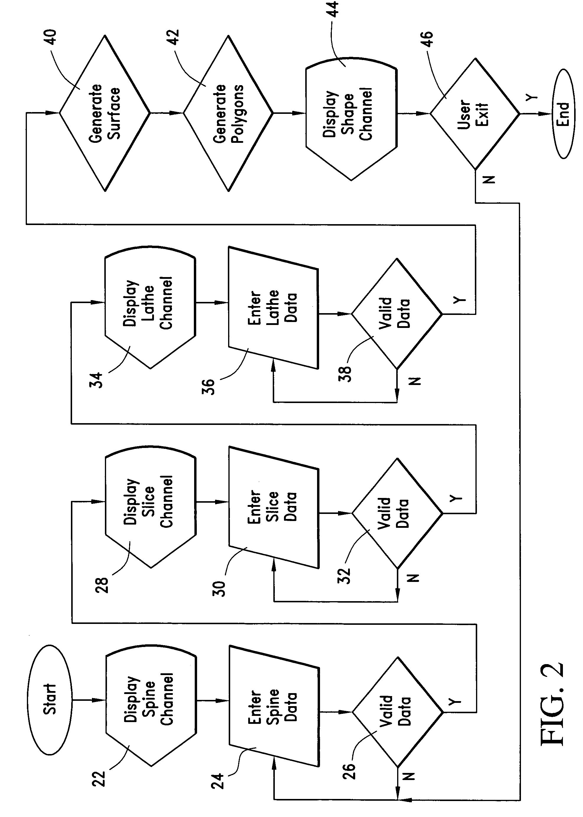
[0044]This invention is represented as C / C++ source code, which is compiled for Windows NT / 2000 using Microsoft Visual C++ 6.0 Developer Studio, and OpenGL version 1.1 libraries which are included as standard with the operating system. This invention is compiled into an executable file (.EXE), a complete application. Using a computer that has the microprocessor based on the Intel Pentium PC or the Athalon PC a user can use the application by “running” or opening the Figment3D.EXE file. The application allows a user with minimal training to create and modify shapes by drawing or selecting primitives, each of which is represented as a single surface. The user can save one or more shape files to diskette...


PUM


Abstract

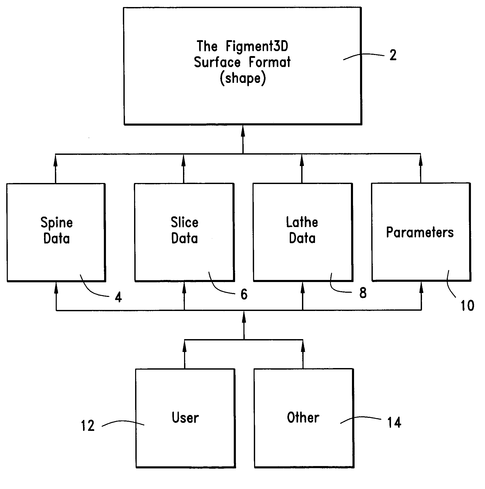
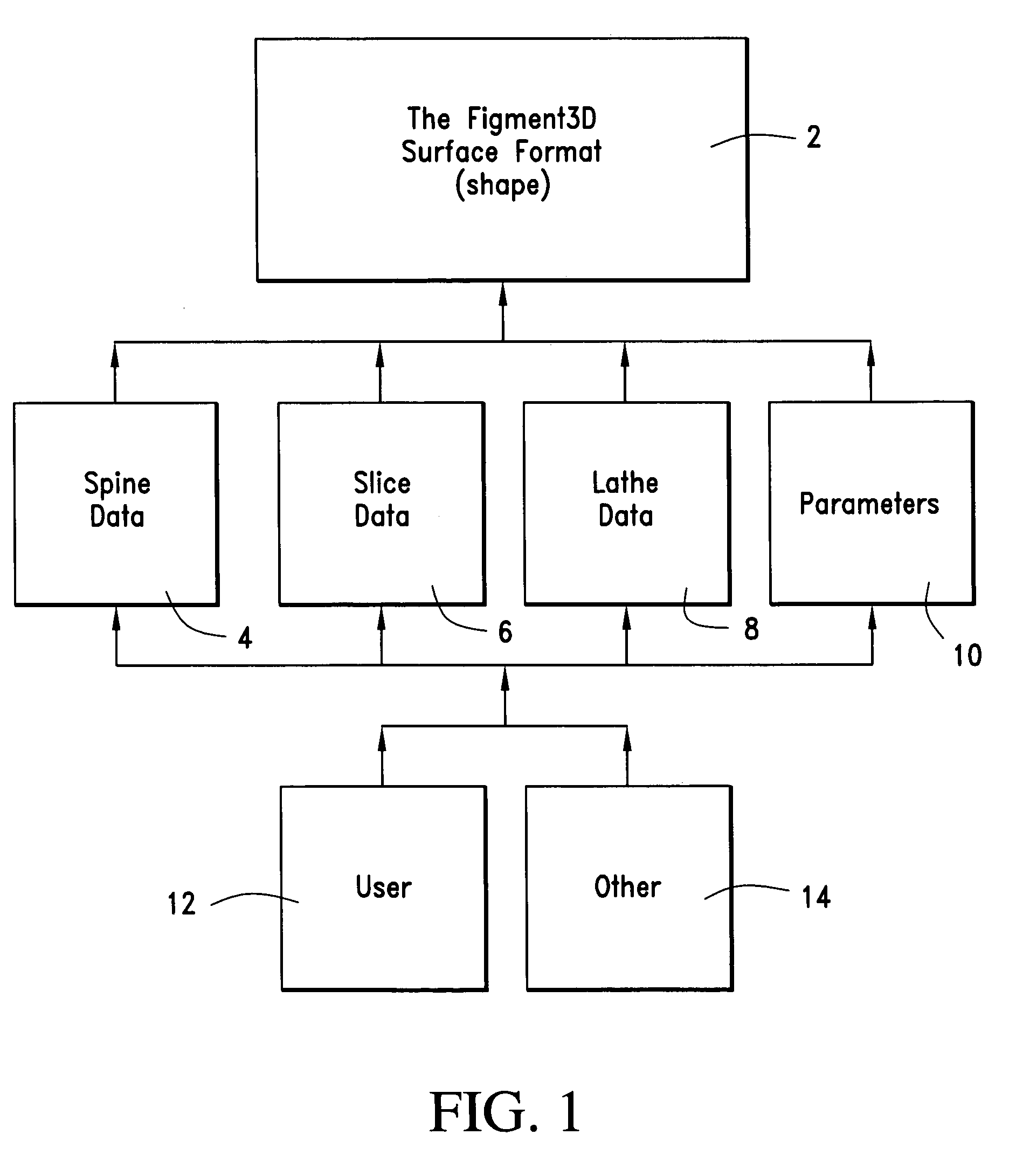
A method of representing n-dimensional parametric surfaces (animated shapes) is provided that expresses all shapes in a consistent manner to reduce storage requirements, support deformation and simplify interaction between shapes. The method, a version of sweeps, represents shapes using a unique combination of three discrete types of (piecewise polynomial) curves: spine (sweeping) curves, slice (section) curves, and lathe (plane) curves, which are combined to create surfaces. The curves required to make simple 3D primitives (i.e. torus, sphere, cube and pyramid) are themselves simple 2D primitives (i.e. line, circle, square, triangle). The storage size of this system's shapes is exponentially smaller than the size of polygonal versions of the same shapes (as a function of the number of polygons). Complex models can be broken into multiple shapes, which are arranged in a tree hierarchy. The shapes of this invention can be tiled with other shapes of this invention (i.e. a row of smokestacks made of bricks). The shapes of this invention can smoothly travel on other shapes of this invention (i.e. a football rolling over arbitrary terrain). This invention supports fast, intuitive creation of shapes such as hand-drawn shapes. This invention is a closed system, providing a suite of operations that can occur in arbitrary order sans approximation errors. When scenes are constructed of parametric building blocks, each represented with the same universal formula, a suite of advanced operations becomes available, providing support critical to advanced software simulations.

Description

RELATED APPLICATION[0001]This application is related to U.S. Provisional Patent Application Ser. No. 60 / 369,824, filed Apr. 4, 2002 in the name of Neil D. McLaughlin, entitled “Apparatus and Method for Generating 3D Images”, and is incorporated herein by reference.BACKGROUND OF THE INVENTION[0002]The traditional (non-Figment3D) method of 3D rendering involves a three-step process of geometry creation (3D tools), geometry rendering (3D engine), and perhaps geometry analysis (physics, collision detection, etc).[0003]In the first step (geometry creation) an “artist” builds models using 3D tools (i.e. Discreet 3DStudio Max, and Alias Maya). These tools provide methods of using curved surfaces, typically handled as piecewise parametric patches, NURBS or Subdivision Surfaces. However the tools normally export models as polygon data: the editing features are often no longer available. Another drawback is that precision issues occur when certain operations such as scaling are performed: som...

Claims


Application Information

Patent Timeline
IPC IPC(8): G06T15/70
CPCG06T17/30G06T17/10
Inventor MCLAUGHLIN, NEIL D.
Owner FIGMENT3D ENTERPRISES
Learn More