
CCD-based biochip reader

a biochip reader and ccd technology, applied in the field of ccd-based biochip readers, can solve the problems of large sample size, large time consumption, and inability to complete analysis, and achieve the effect of rapid and efficient detection

Inactive Publication Date: 2007-02-06
KAIWOOD TECH
View PDF4 Cites 12 Cited by
  • Summary
  • Abstract
  • Description
  • Claims
  • Application Information

AI Technical Summary

Benefits of technology

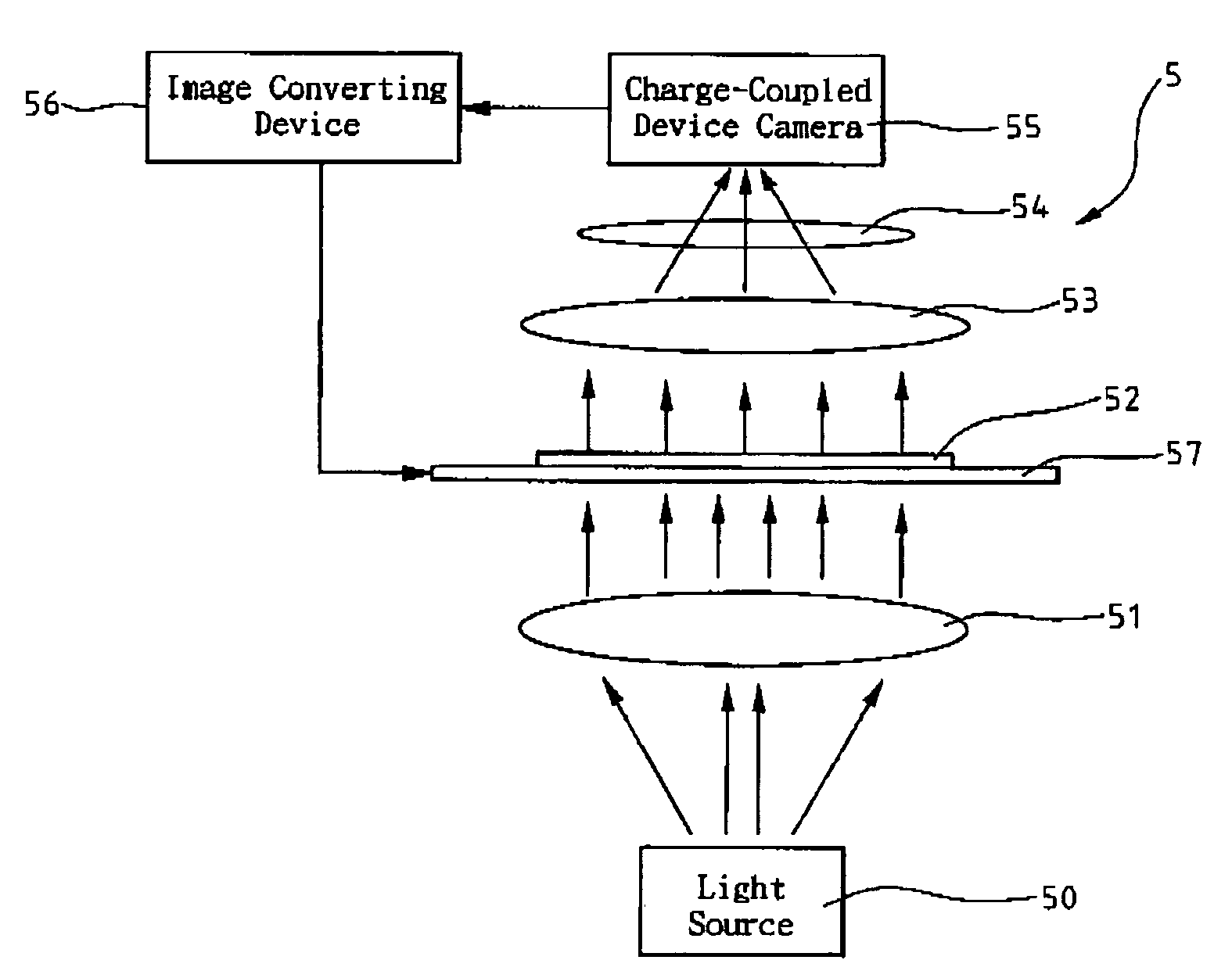
[0009]A primary object of the present invention is to provide a CCD-based biochip reader by which samples are excited with wide parallel laser beams and images are collected and analyzed through a large-area charge-coupled device camera. Therefore, detection is rapid and efficient.
[0011]Wide parallel laser beams are produced by the laser and through the collimating lens of the present invention, and excite all samples on the biochip with high efficiency at the same time. In addition, time for analysis is saved when fluorescent images of a large area on biochips are collected and analyzed through the charge-coupled device camera.

Problems solved by technology

However, it takes much time to complete analysis of a large number of samples.
Moreover, errors arise since so many samples cannot be analyzed at the same time.
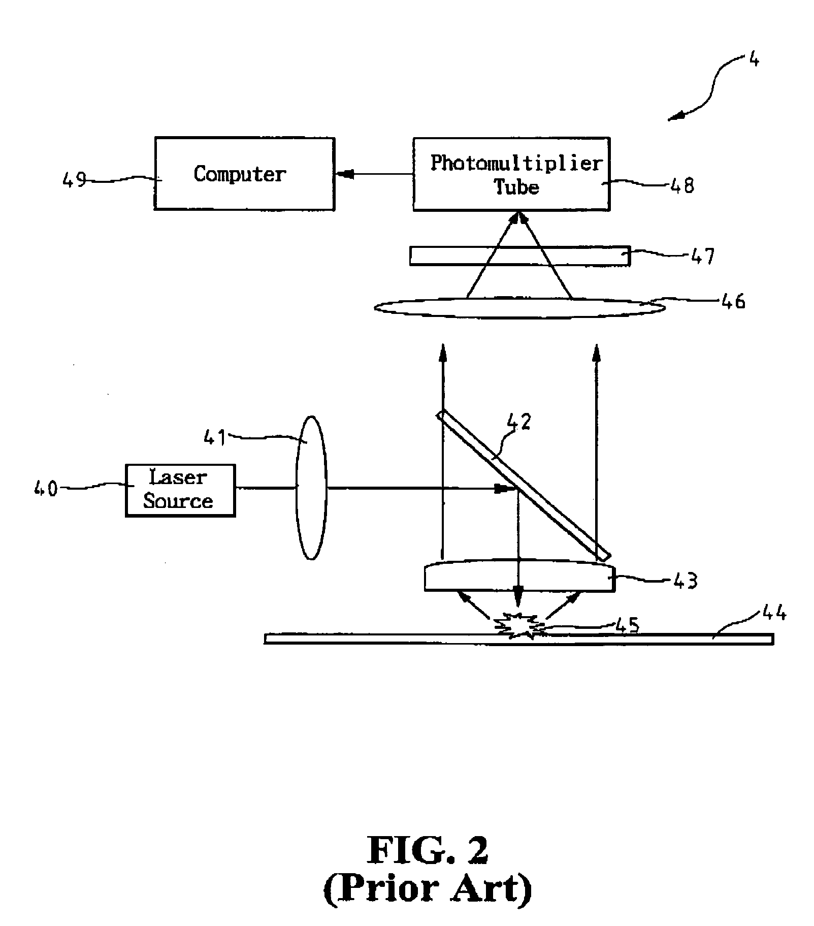
The prior art biochip is disadvantageous for it takes a long time to scan all the samples and obtain the images.
Although it is not necessary to scan all the samples on the biochip in this kind of biochip reader, the white-light excitation is not efficient and the sensitivity is lower than the laser / PMT based systems.

Method used


Image

  • CCD-based biochip reader
  • CCD-based biochip reader
  • CCD-based biochip reader

Examples


Embodiment Construction

[0017]Preferred embodiments of the present invention will now be described in detail below with reference to the accompanying drawings. FIG. 3 is a schematic view showing an embodiment of a CCD-based biochip reader (5) of the present invention. The CCD-based biochip reader (5) comprises a light source (50), such as a laser source, for emitting flat-top energy light beams, which means the energy distribution of the light beams is non-Gaussian (uniform) distribution in intensity; a collimating lens (51) for converting said light beams into wide parallel rays of light (if the laser contains a collimator, it does not need to add this collimator), passing said wide parallel flat-top energy rays of light through a biochip (52) and exciting fluorescence from fluorescent targets on the biochip (52); a focusing lens (53) for focusing the fluorescence (if the CCD camera with a lens head, it does not need a focusing lens); a filter (54) for filtering out said parallel rays of light; a large-ar...


PUM

PropertyMeasurementUnit
fluorescenceaaaaaaaaaa
charge-aaaaaaaaaa
energyaaaaaaaaaa

Abstract

A CCD-based biochip reader includes a light source for emitting light beams, a collimating lens for converting the light beams into wide parallel rays of light, passing said wide parallel rays of light through a biochip and exciting fluorescence from fluorescent targets on the biochip, a focusing lens for focusing the fluorescence, a filter for filtering out said parallel rays of light, and a charge-coupled device camera for generating images from said fluorescence. For recording intensity of the fluorescence from the fluorescent targets, images of the charge-coupled device camera is converted into digital data through an image converting device. Wide parallel laser beams are produced by the laser and through the collimating lens, and excite all samples on the biochip with high efficiency at the same time. In addition, time for analysis is saved when fluorescent images of a large area on biochips are collected and analyzed through the charge-coupled device camera.

Description

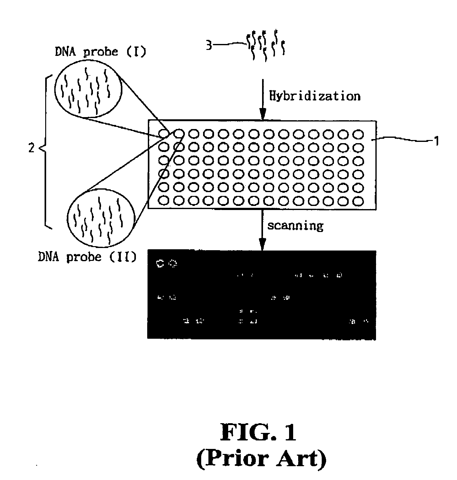
BACKGROUND OF THE INVENTION[0001]1. Field of the Invention[0002]The present invention relates to a CCD-based biochip reader, particularly to a biochip reader with a charge-coupled device (CCD) camera to collect and analyze images of fluorescence from biochips.[0003]2. The Prior Arts[0004]Tools and methods are designed to detect and analyze nucleic acids and proteins in the cellular and molecular biology field. However, it takes much time to complete analysis of a large number of samples. Moreover, errors arise since so many samples cannot be analyzed at the same time. For accelerating the progress of the related research, especially the genomic and proteomic research, high-throughput tools for efficient analysis are manufactured, of which an example is biochips. Biochips are applied to gene expression, drug selection and disease diagnosis in both basic research and clinical application fields.[0005]There are three kinds of biochips that are currently known as DNA chip, lab-on-a-chip...

Claims


Application Information

Patent Timeline
Patent Type & Authority Patents(United States)
IPC IPC(8): G01N21/25G01N21/64
CPCG01N21/6428G01N21/6456G01N21/6452
Inventor WANG, JIANN-HUACHUANG, TSUNG-KAIWU, TZU-CHIANGCHUANG, CHIEN-HO
Owner KAIWOOD TECH
Learn More