Method and apparatus for distributing a self-synchronized clock to nodes on a chip

Inactive Publication Date: 2007-02-06
AGERE SYST GUARDIAN
View PDF10 Cites 27 Cited by
  • Summary
  • Abstract
  • Description
  • Claims
  • Application Information

AI Technical Summary

Benefits of technology

[0013]The present invention permits dynamic adjustments to the delay control circuit as operating conditions shift by feeding back the destination clock and estimating the round trip delay time. Thus, clock signals arriving at individual nodes on the in...

Problems solved by technology

The round trip travel time includes delays attributable to bot...

Method used


Image

  • Method and apparatus for distributing a self-synchronized clock to nodes on a chip
  • Method and apparatus for distributing a self-synchronized clock to nodes on a chip
  • Method and apparatus for distributing a self-synchronized clock to nodes on a chip

Examples


Embodiment Construction

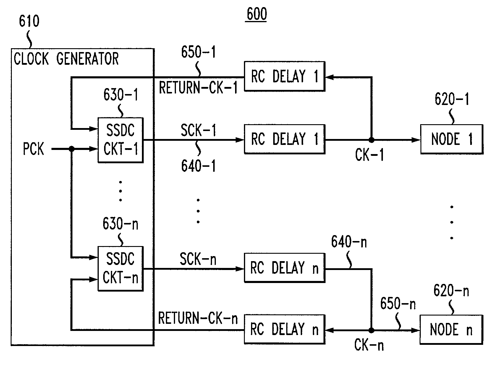
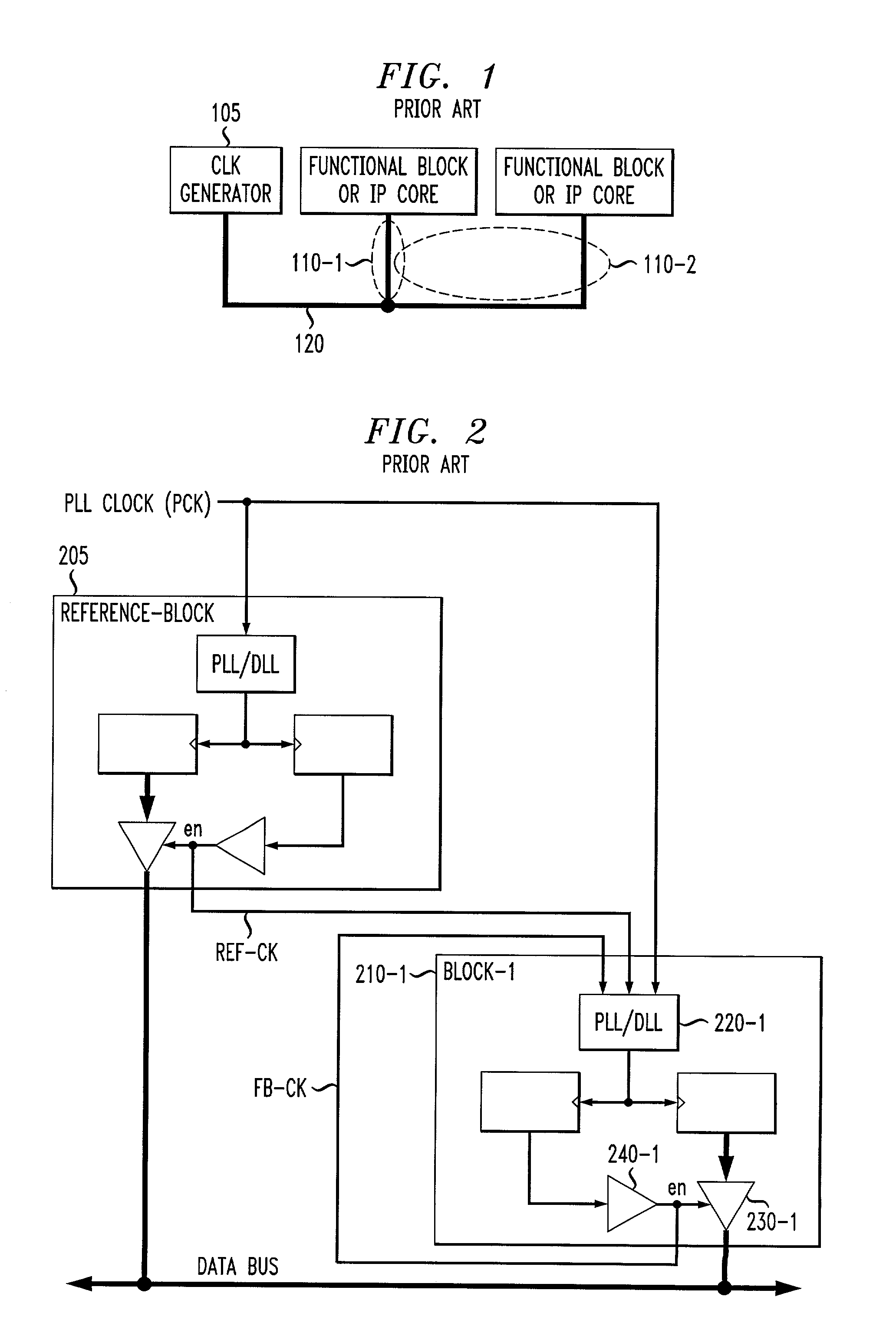
[0023]FIG. 5 is a schematic block diagram illustrating an exemplary SoC 500 where the present invention can operate. The exemplary SoC 500 includes a bus 510 that interconnects various nodes 520-1 through 520-N (multiple core devices), collectively referred to as nodes 520, on the chip 500. The nodes 520 may be embodied, for example, as memory devices, micro-controllers, microprocessors and digital signal processors (DSPs). When an SoC 500 includes multiple nodes 520 communicating over a common bus 510, an Arbiter 550 is often used to determine which node 520 should actively drive the bus 510 at a particular time. Multi-source / multi-sink control signals, such as acknowledgement (ACK), data-valid, interrupt and error signals, are often employed to control communications on the SoC bus 510. All of the various nodes 520 and the Arbiter 550 typically operate synchronously with respect to a common clock 560.

[0024]According to one feature of the present invention, an automatic clock skew ...


PUM


Abstract

A method and apparatus are disclosed for dynamically reducing clock skew among various nodes on an integrated circuit. The disclosed clock skew reduction technique dynamically estimates the clock delay to each node and inserts a corresponding delay for each node such that the clock signals arriving at each node are all in phase with a global clock (or 180° out of phase). Delays attributable to both the wire RC delays and the clock buffer delays are addressed. A feedback path for the clock signal associated with each node allows the round trip travel time of the clock signal to be estimated. When the length of the feedback path matches the length of the primary clock path, the clock skew present at the corresponding node can be estimated as fifty percent (50%) of the round trip delay time. Dynamic adjustments to the delay control circuit are permitted as operating conditions shift. Clock signals arriving at individual nodes on the integrated circuit remain in phase with the global PLL clock (PCK), regardless of variations in the operating voltage or temperature (or both).

Description

CROSS-REFERENCE TO RELATED APPLICATIONS [0001]The present invention is related to U.S. patent application Ser. No. 09 / 788,582, entitled “Method and Apparatus far Transferring Multi-Source / Multi-Sink Control Signals Using a Differential Signaling Technique,” U.S. patent application Ser. No. 09 / 785,602, entitled “Method and Apparatus for Distributing Multi-Source / Multi-Sink Control Signals Among Nodes on a Chip,” U.S. patent application Ser. No. 09 / 785,653, entitled “Bidirectional Bus Repeater for Communications on a Chip,” and U.S. patent application Ser. No. 09 / 785,592, entitled “On-Chip Method and Apparatus for Transmission of Multiple Bits Using Quantized Voltage Levels,” each filed contemporaneously herewith, assigned to the assignee of the present invention and incorporated by reference herein.FIELD OF THE INVENTION [0002]The present invention relates generally to clock distribution techniques, and more particularly, to clock distribution techniques for synchronizing operations ...

Claims


Application Information

Patent Timeline
IPC IPC(8): G06F1/04G06F1/10
CPCG06F1/10
Inventor LEE, HYUNNGUYEN, HANPHAM, LAI Q.
Owner AGERE SYST GUARDIAN
Why Eureka
Try Eureka