Laser-based, multiphoton-excitation-type optical examination apparatus
a multi-photon-excitation, optical examination technology, applied in the direction of optical radiation measurement, luminescent dosimeters, instruments, etc., can solve the problems of inability to reduce the size of the measurement head, the overall size of the apparatus becomes large, and the adjustment of the pulse stretcher and the pulse compressor must be carried out each time, so as to efficiently generate the multi-photon-excitation effect, the effect of easy adjustmen
- Summary
- Abstract
- Description
- Claims
- Application Information
AI Technical Summary
Benefits of technology
Problems solved by technology
Method used
Image
Examples
first embodiment
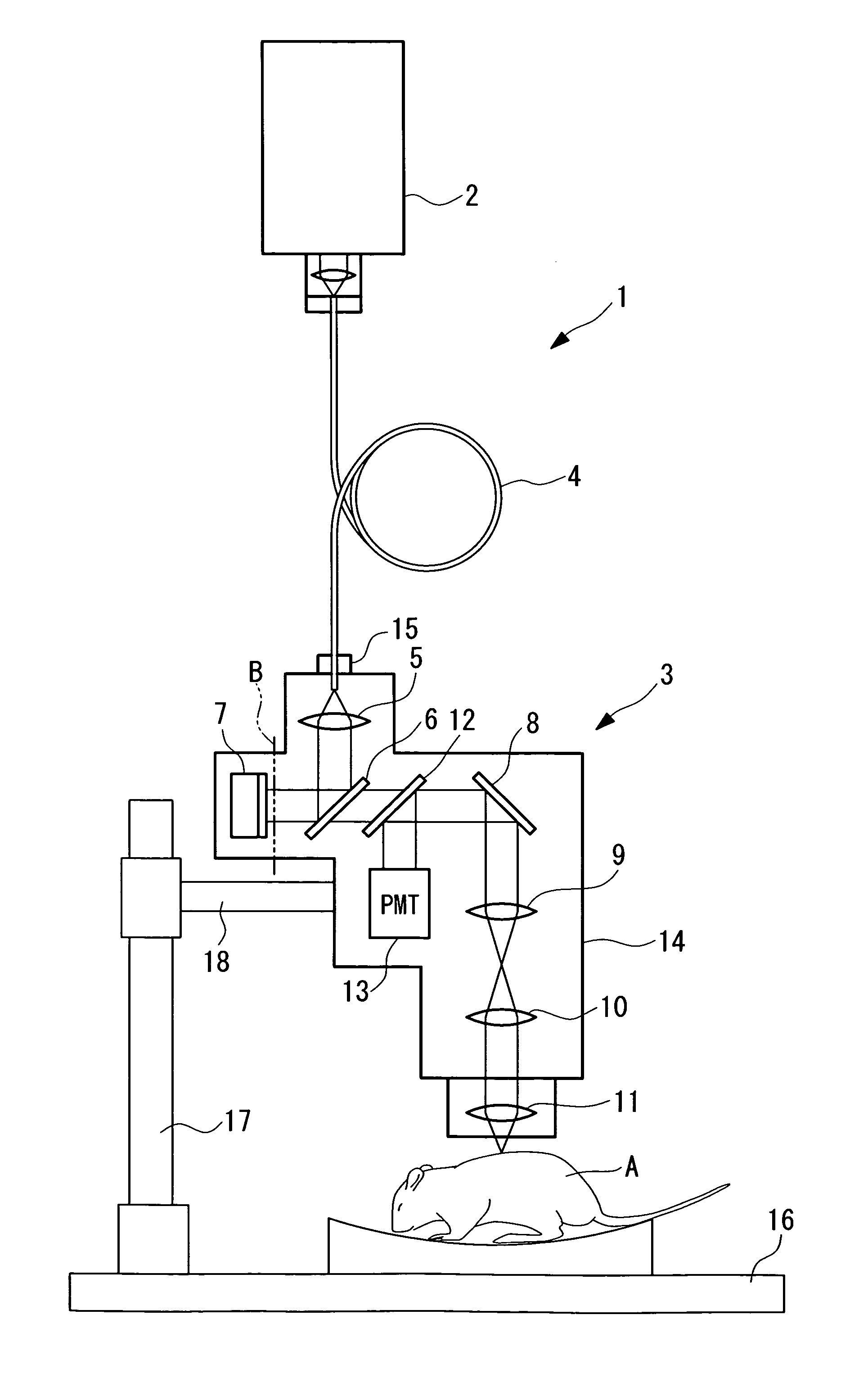
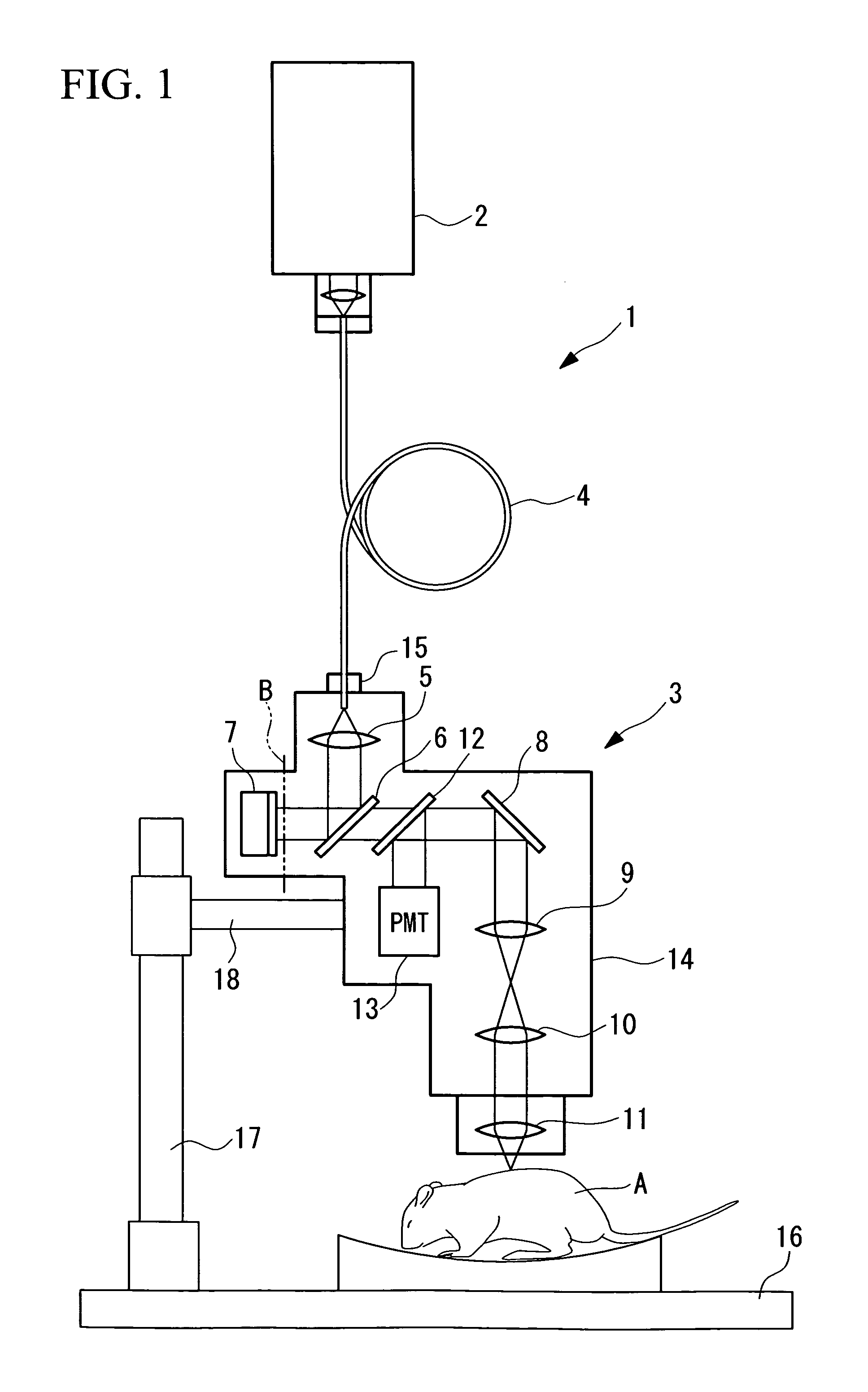
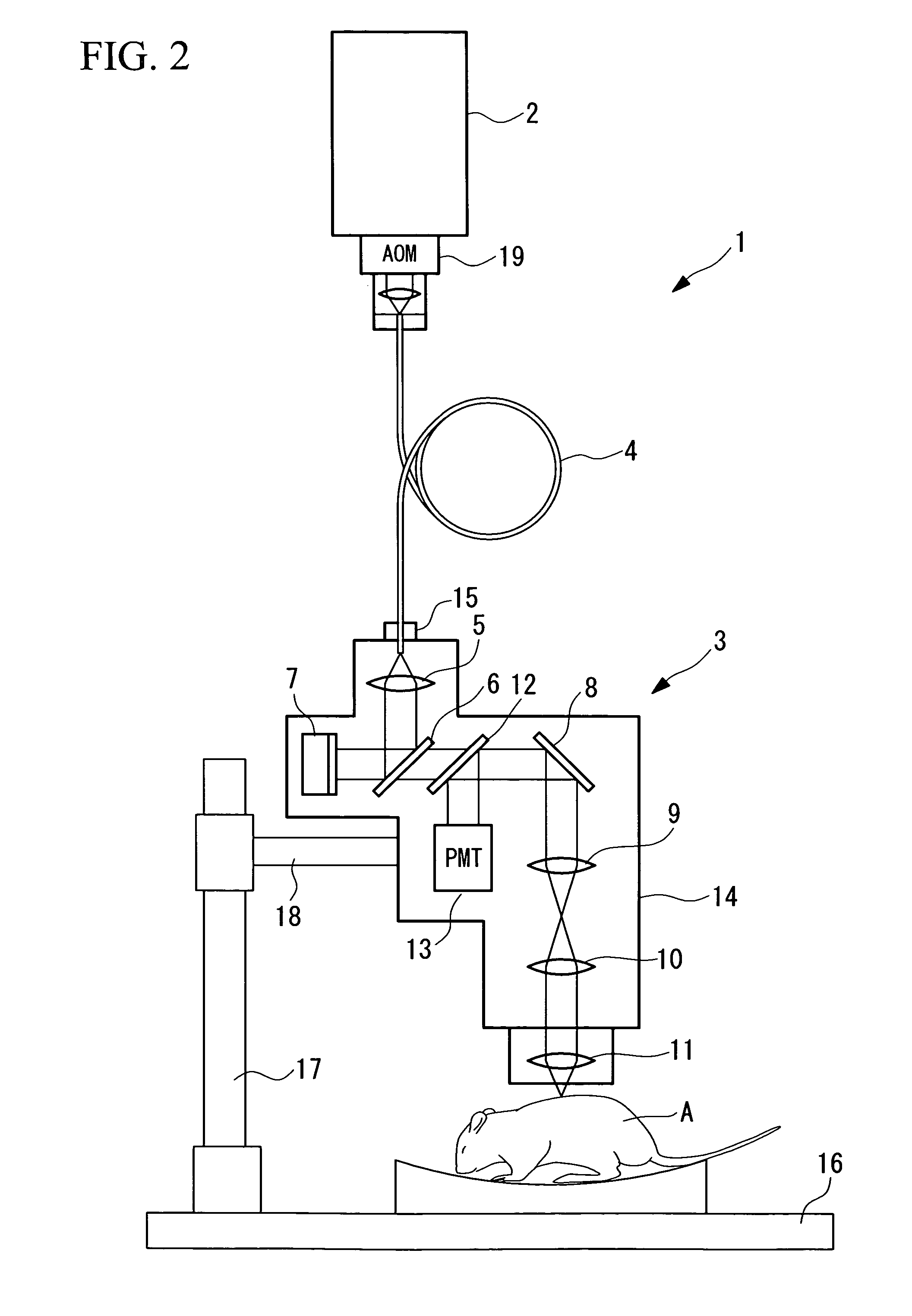
[0057]A multiphoton-excitation-type examination apparatus 1 according to a first embodiment of the present invention will be described below with reference to FIG. 1.
[0058]As shown in FIG. 1, the multiphoton-excitation-type examination apparatus 1 according to this embodiment is formed of a laser light source 2, a measurement head 3, and an optical fiber 4 that connects the laser light source 2 and the measurement head 3. The laser light source 2 is a light source that generates near-infrared ultrashort pulses of light, for example, with a pulse width of about 100 fs (femtoseconds), such as a Ti:sapphire laser light source.
[0059]The measurement head 3 includes a collimator lens 5 that collimates the ultrashort pulsed light transmitted by the optical fiber 4; a half-mirror 6 that reflects the collimated light from the collimator lens 5; a dispersion-compensating mirror (dispersion-compensating member) 7 on which the light reflected by the half-mirror 6 is incident; an optical scannin...
second embodiment
[0077]Next, a multiphoton-excitation-type examination apparatus 20 according to a second embodiment of the present invention will be described below with reference to FIG. 3.
[0078]Parts in the description of this embodiment having the same configuration as those in the multiphoton-excitation-type examination apparatus 1 according to the first embodiment described above are assigned the same reference numerals, and a description thereof is omitted here.
[0079]The multiphoton-excitation-type examination apparatus 20 according to this embodiment differs from the multiphoton-excitation-type examination apparatus 1 according to the first embodiment in that a first dispersion-imparting member 21 is provided between the laser light source 2 and the optical fiber 4, and a dispersion-imparting member provided inside the measurement head 3 is a second dispersion-imparting member 22 for imparting positive group velocity dispersion. Reference numeral 23 represents a dichroic mirror that is desig...
third embodiment
[0084]Next, a multiphoton-excitation-type examination apparatus 30 according to a third embodiment of the present invention will be described below with reference to FIGS. 5 and 6.
[0085]Parts in the description of this embodiment having the same configuration as in the multiphoton-excitation-type examination apparatus 20 according to the second embodiment described above are assigned the same reference numerals, and a description thereof shall be omitted here.
[0086]The multiphoton-excitation-type examination apparatus 30 according to this embodiment differs from the multiphoton-excitation-type examination apparatus 20 according to the second embodiment in that a second dispersion-imparting member 31 serving as the dispersion-compensating member produces positive group velocity dispersion, and an adjusting mechanism 32 is provided for adjusting the group velocity dispersion thereof.
[0087]For example, as shown in FIG. 5 and FIG. 6, a member that can select different amounts of dispers...
PUM
| Property | Measurement | Unit |
|---|---|---|
| wavelength range | aaaaa | aaaaa |
| wavelength | aaaaa | aaaaa |
| wavelength | aaaaa | aaaaa |
Abstract
Description
Claims
Application Information
 - R&D
- Intellectual Property
- Life Sciences
- Materials
- Tech Scout
- Unparalleled Data Quality
- Higher Quality Content
- 60% Fewer Hallucinations
Browse by: Latest US Patents, China's latest patents, Technical Efficacy Thesaurus, Application Domain, Technology Topic, Popular Technical Reports.
© 2025 PatSnap. All rights reserved.Legal|Privacy policy|Modern Slavery Act Transparency Statement|Sitemap|About US| Contact US: help@patsnap.com


