Internal combustion engine and control method thereof

a technology of combustion engine and control method, which is applied in the direction of electrical control, machines/engines, output power, etc., can solve the problem of difficult to reliably supply the catalyst with the amount of air necessary for activating (warming) the catalyst, and achieve the effect of reducing exhaust emissions and reliably activating the catalyst early

Inactive Publication Date: 2007-02-20
TOYOTA JIDOSHA KK
View PDF22 Cites 36 Cited by
  • Summary
  • Abstract
  • Description
  • Claims
  • Application Information

AI Technical Summary

Benefits of technology

[0008]It is an object of the invention to provide an internal combustion engine and a control method thereof, which make it possible to reliably activate a catalyst early, and to suitably reduce exhaust emissions.
[0010]According to the first aspect of the invention, the internal combustion engine includes the supercharging pressure setting device which changes the supercharging pressure generated by the turbocharger, and the valve opening characteristic setting device which changes the valve opening characteristic of at least one of the intake valve and the exhaust valve. In the internal combustion engine, the valve overlap period during which both of the intake valve and the exhaust valve are opened is set while the pressure of the air taken into the combustion chamber is set to a value larger than the back pressure until it is determined that the catalyst has been activated, for example, immediately after the engine is started. Thus, so-called blow-by from the intake port to the exhaust port is reliably promoted, and a sufficient amount of air (oxygen) can be delivered to the catalyst together with unburned fuel. As a result, in the internal combustion engine, so-called after-burning in the catalyst and an exhaust pipe can be promoted, and the temperature of exhaust gas can be increased. Therefore, the catalyst can be activated early, and the exhaust emissions can be suitably reduced.
[0013]In the first aspect of the invention, the controller may cause the in-cylinder injector to inject the fuel also during an exhaust stroke until it is determined that the catalyst has been activated. With the configuration, since the in-cylinder injector injects the fuel also during the exhaust stroke in addition to normal fuel injection (in-cylinder injection), the temperature of exhaust gas discharged from the combustion chamber can be increased by promoting combustion in the combustion chamber, and a sufficient amount of air (oxygen) can be delivered to the catalyst together with unburned fuel.
[0015]With the aforementioned configuration, since air and the fuel supplied from the fuel injection device are uniformly mixed at the intake port, blow-by of the uniform and lean mixture from the intake port toward the exhaust port is promoted. Thus, in the internal combustion engine, the catalyst can be efficiently activated by delivering a sufficient amount of air (oxygen) to the catalyst together with unburned fuel, and promoting so-called after-burning.
[0016]In the first aspect of the invention, the fuel injection device may include a port injector for injecting the fuel into the intake port, and an in-cylinder injector for injecting the fuel directly into the combustion chamber. Also, the controller may cause the port injector to inject the fuel such that an air-fuel ratio of the mixture in the intake port (and the exhaust port) becomes lean and may cause the in-cylinder injector to inject the fuel until it is determined that the catalyst has been activated. With the configuration, the temperature of exhaust gas can be increased by delivering a sufficient amount of air (oxygen) to the catalyst together with unburned fuel. Accordingly, the catalyst can be activated early, and exhaust emissions can be suitably reduced.
[0019]According to the invention, it is possible to provide the internal combustion engine and control method thereof, which makes it possible to reliably activate the catalyst early and to suitably reduce exhaust emissions.

Problems solved by technology

However, as described above, even if the fuel is injected directly into the combustion chamber during the exhaust stroke or the compression stroke, it is difficult to reliably supply the catalyst with air of an amount necessary for activating (warming) the catalyst.

Method used


Image

  • Internal combustion engine and control method thereof
  • Internal combustion engine and control method thereof
  • Internal combustion engine and control method thereof

Examples


Embodiment Construction

[0027]Hereinafter, an exemplary embodiment of the invention will be described with reference to accompanying drawings.

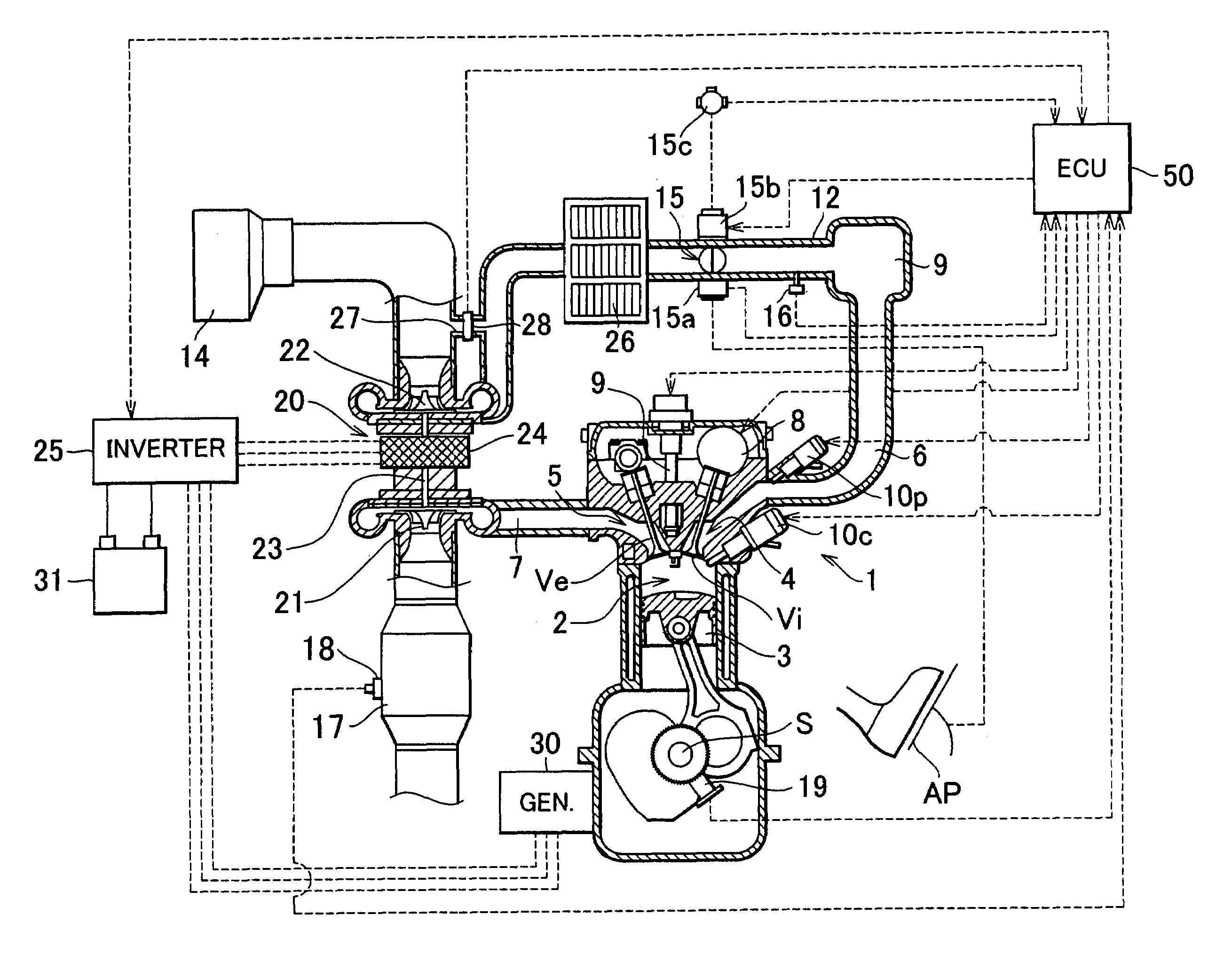
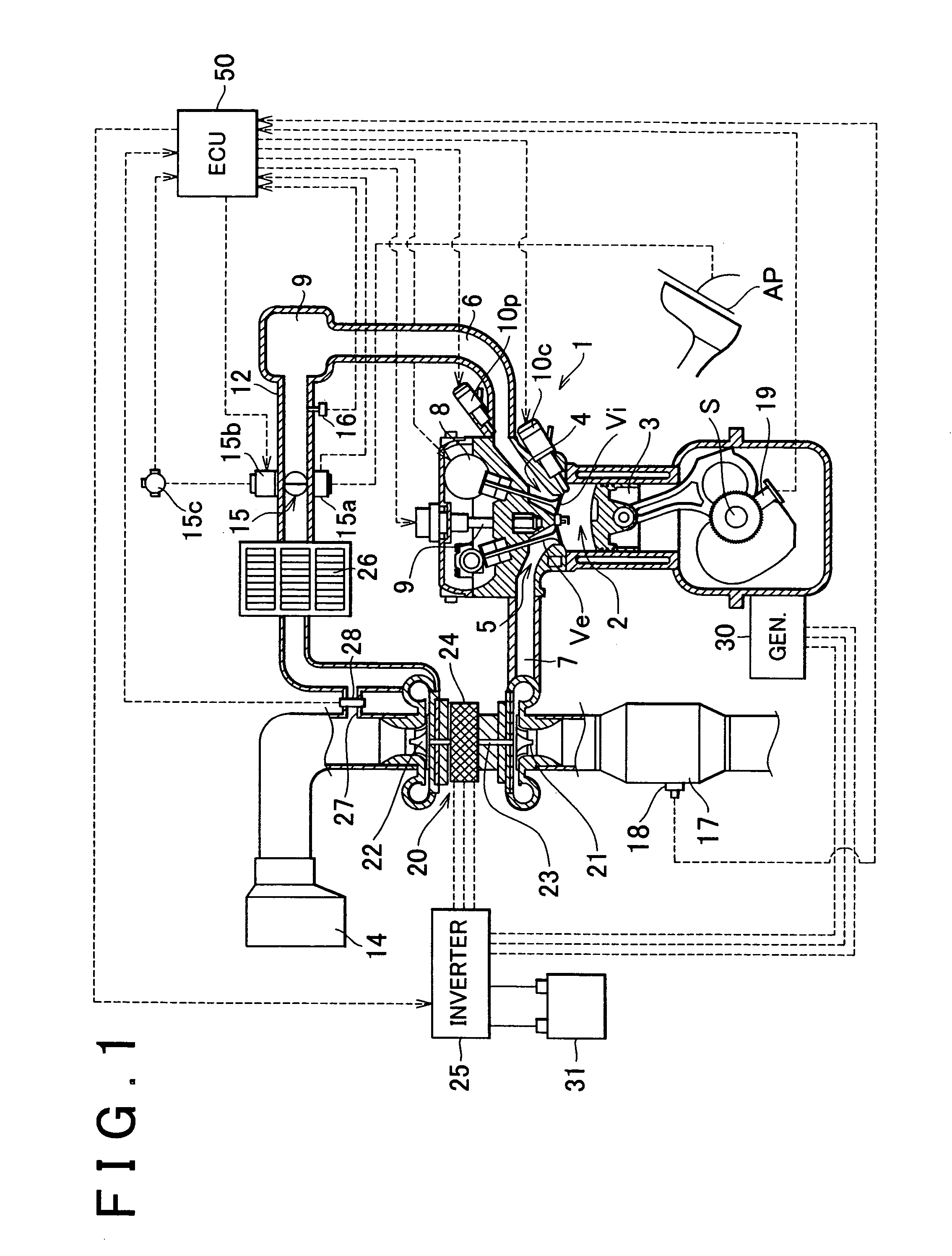
[0028]FIG. 1 is a schematic diagram showing an internal combustion engine according to the invention. An internal combustion engine 1 shown in FIG. 1 is configured as a multi-cylinder internal combustion engine for a vehicle (for example, a four-cylinder internal combustion engine. However, FIG. 1 shows only one cylinder). A piston 3 is reciprocated using combustion of an air-fuel mixture in each combustion chamber 2, whereby power is obtained from a crank shaft S. In the embodiment, the internal combustion engine 1 is described as a so-called gasoline engine. However, the invention is not limited to the gasoline engine. It is apparent that the invention can be applied to a diesel engine.

[0029]As shown in FIG. 1, each intake port 4 that is continuous with each combustion chamber 2 is connected to an intake pipe 6 via an intake manifold. Each exhaust port 5 that is co...


PUM


Abstract

An internal combustion engine in which power is generated by burning a mixture of fuel supplied from a port injector and / or an in-cylinder injector and air in a combustion chamber, includes a valve drive mechanism which can change a valve opening characteristic of at least one of an intake valve and an exhaust valve; a turbocharger which supercharges air taken into the combustion chamber; a turbo motor which changes supercharging pressure generated by the turbocharger; a catalyst device including a catalyst which purifies exhaust gas discharged from the combustion chamber; and an ECU which controls the turbo motor such that pressure of the air taken into the combustion chamber becomes larger than back pressure until it is determined that the catalyst has been activated, and which sets a valve overlap period during which both of the intake valve and the exhaust valve are opened.

Description

INCORPORATION BY REFERENCE[0001]The disclosure of Japanese Patent Application No. 2003-381730 filed on Nov. 11, 2003 including the specification, drawings and abstract is incorporated herein by reference in its entirety.BACKGROUND OF THE INVENTION[0002]1. Field of the Invention[0003]The invention relates to an internal combustion engine in which power is generated by burning an air-fuel mixture in a combustion chamber, and a control method thereof. More particularly, the invention relates to an internal combustion engine and a control method thereof, which make it possible to activate a catalyst for purifying exhaust gas discharged from a combustion chamber early.[0004]2. Description of the Related Art[0005]Recently, it has become more and more important to reduce exhaust emissions such as HC, for example, immediately after an engine is started in a cold state, since enforcement of the emission control and the like is strengthened. Therefore, as disclosed in Japanese Patent Applicat...

Claims


Application Information

Patent Timeline
Patent Type & Authority Patents(United States)
IPC IPC(8): F01N3/00F02B37/00F01N3/20F01N3/24F02B37/10F02D13/02F02D23/02F02D41/00F02D41/02F02D41/06F02D41/34F02D41/40F02D43/00F02D45/00
CPCF02D41/0007F02D41/3094F02D41/025F02B37/10F02B39/10F02D13/0261Y02T10/26F02D41/405F02D2041/001Y02T10/144Y02T10/12
Inventor MIYASHITA, SHIGEKI
Owner TOYOTA JIDOSHA KK
Why Eureka
Try Eureka