
High temperature protection of fuel cell system combustor and other components via water or water vapor injection

a fuel cell and combustor technology, applied in the field of fuel cell combustors, can solve the problems of long-term system reliability degradation, component or system failure, excessive high temperature in the burner, etc., and achieve the effects of reducing energy consumption, superior heat transfer and heat absorption characteristics, and reducing manufacturing costs

Active Publication Date: 2007-02-20
CUMMINS ENTERPRISE LLC
View PDF6 Cites 7 Cited by
  • Summary
  • Abstract
  • Description
  • Claims
  • Application Information

AI Technical Summary

Benefits of technology

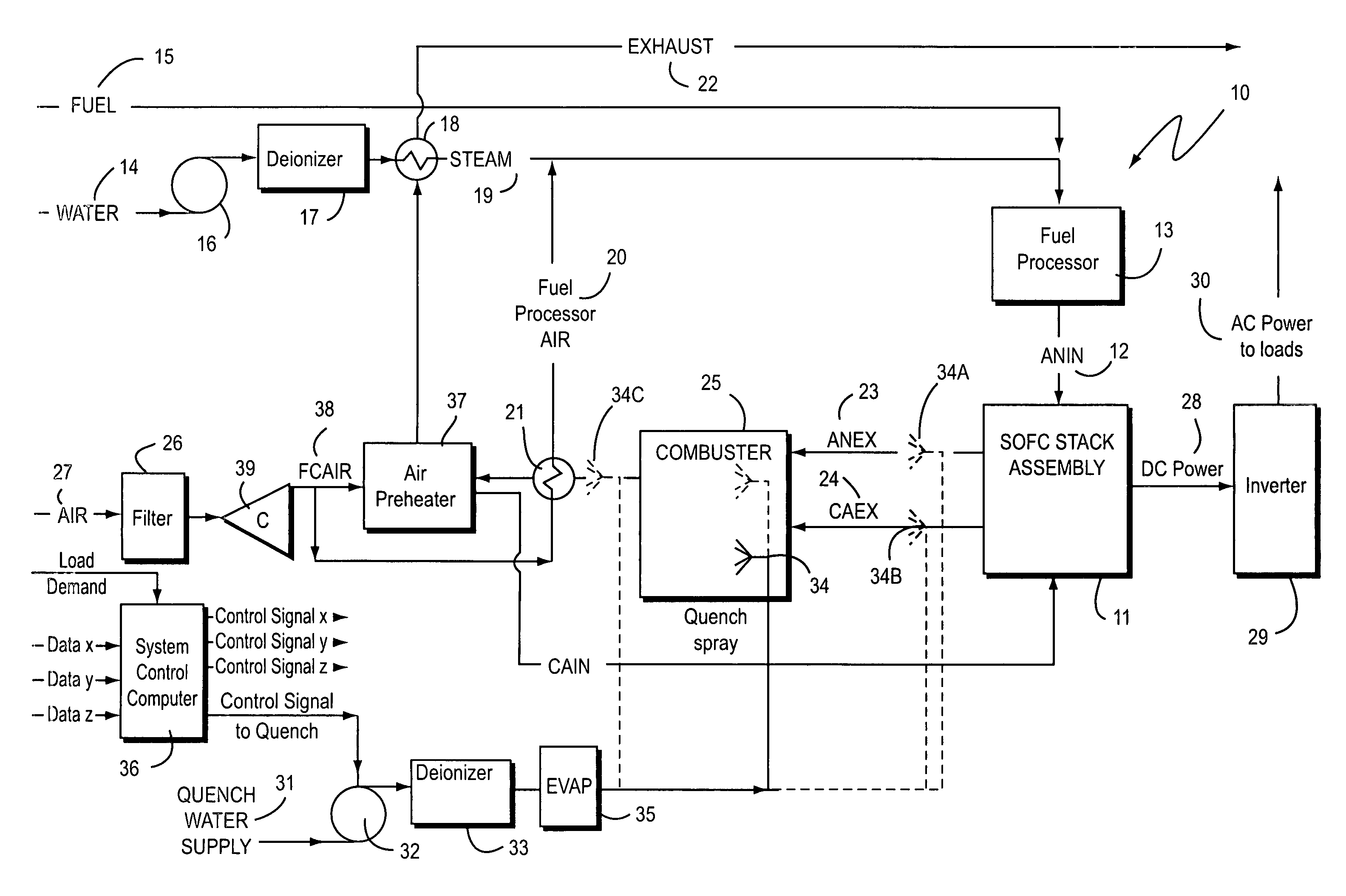
The present invention is about controlling the temperature in a fuel cell system's tail gas burner using water or water vapor. This is done by injecting the water or water vapor into the combustion chamber through a nozzle or multiple nozzles. The physical properties of water and water vapor make them superior heat transfer and absorption compared to currently used cooling fluids, which means they require less energy and provide better component protection without affecting system efficiency. The invention includes a water or water vapor source, a means of guiding the flow, a means of regulating the flow and pressure, and a nozzle or multiple nozzles for injection. The nozzles provide high atomization for liquid water or a well-dispersed spray pattern for water vapor. The control algorithm reacts to combustor temperature, changes in power production, and other system parameters to regulate combustor temperature. This allows for quicker response times without consuming significant amounts of water.

Problems solved by technology

During some operating modes, reactant mixtures exist in quantities that can lead to excessively high temperatures in the burner and other equipment downstream of a fuel cell stack.
These high temperatures can lead to long term system reliability degradation and even component or system failures.
However, these materials are generally expensive and / or difficult to fabricate.
This also complicates the construction of the burner and may decrease efficiency.
This requires a larger oxidant pumping device, which increases system cost and decreases system efficiency, since the oxidant most used in fuel cell systems, i.e., air, is not a good heat transfer medium and gasses require more energy to move than do liquids.

Method used


Image

  • High temperature protection of fuel cell system combustor and other components via water or water vapor injection
  • High temperature protection of fuel cell system combustor and other components via water or water vapor injection
  • High temperature protection of fuel cell system combustor and other components via water or water vapor injection

Examples


Embodiment Construction

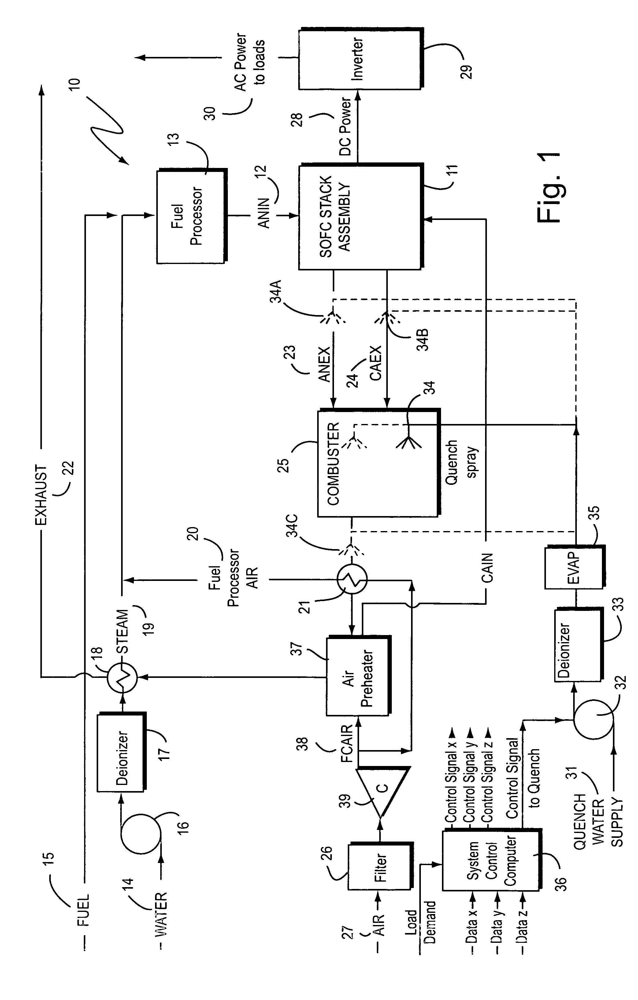
[0012]FIG. 1 is an example of a process flow schematic of a fuel cell combustor system 10 using the water or water vapor injection temperature control system and method of the present invention. System 10 includes a solid oxide fuel cell (“SOFC”) stack assembly 11 into which fuel 12, designated as “anode in” (“ANIN”), is inputted. The fuel 12 inputted to stack assembly 11 is produced by a fuel processor 13, which receives both fuel 15 and steam 19 to generate stack fuel 12. Steam 19 is produced from water 14, which is pumped by a pump 16 through a deionizer 17 into a heat exchanger 18. The deionized water is turned into steam 19 using heat from hot gas input into heat exchanger 18 from an air preheater 23. Steam 19 is also mixed with fuel processor air 20 produced by a second heat exchanger 21 receiving heat from hot gas from a fuel cell tail gas combustion chamber 25 connected to stack assembly 11.

[0013]Stack assembly 11 exhausts excess stack reactants, which include a fuel stream ...


PUM

PropertyMeasurementUnit
temperatureaaaaaaaaaa

Abstract

A system and method are disclosed for high temperature protection of combustor and other components by controlling the temperature of combustion chamber gases in a fuel cell system tail gas burner using a nozzle or plurality of nozzles to inject water or water vapor upstream, downstream or directly into the combustion chamber. A variable speed pump, actuated valve or other flow metering device regulates the supply of water or water vapor to the nozzles. For the case of water vapor, an evaporator is required between the pump and nozzles. Flow regulation is effected by a control algorithm that reacts to combustor temperature, changes in the power production of the fuel cell system and / or other related system parameters.

Description

BACKGROUND OF THE INVENTION[0001]The present invention is directed to fuel cell combustors, and, in particular, to a system and method for injecting water or water vapor into a fuel cell tail gas combustion chamber to regulate combustion temperature.[0002]Fuel cell systems often use a tail gas burner to combust excess stack reactants. During some operating modes, reactant mixtures exist in quantities that can lead to excessively high temperatures in the burner and other equipment downstream of a fuel cell stack. These high temperatures can lead to long term system reliability degradation and even component or system failures.[0003]One method of countering this problem has been to construct the combustion chamber from materials that are tolerant to the high temperatures that may occur. These materials are typically either special metal alloys, ceramics or some combination thereof. However, these materials are generally expensive and / or difficult to fabricate.[0004]Another method of c...

Claims


Application Information

Patent Timeline
Patent Type & Authority Patents(United States)
IPC IPC(8): H01M8/04G06F19/00H01M8/12
CPCH01M8/04007H01M8/04373H01M8/04738H01M8/04768H01M8/04776H01M8/04388H01M8/04395Y02E60/50H01M8/04626H01M8/04447
Inventor FERRALL, JOSEPH FRANCISFENGLER, WOLFGANG ALANPOWERS, JAMES DANIELSOKOLOV, PAVEL ALEXANDROVICH
Owner CUMMINS ENTERPRISE LLC
Learn More