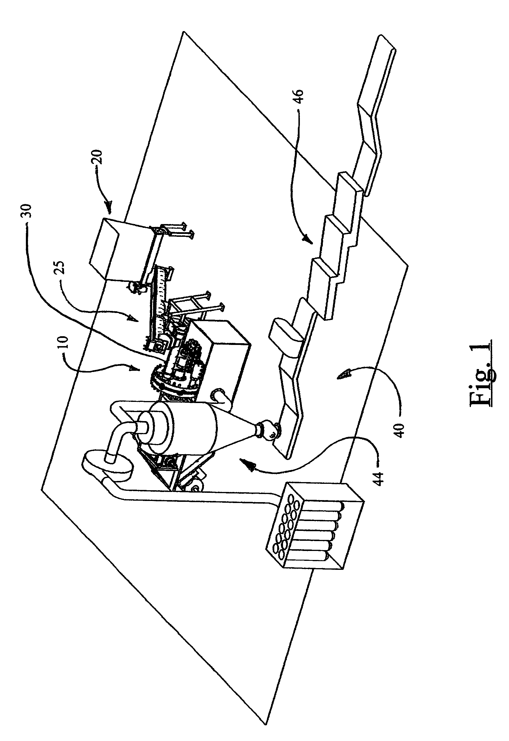
[0013]The present invention improves upon existing tire shredding and grinding technology and provides a single apparatus capable of reducing scrap tires, in whole or in shredded form, to
crumb rubber on the order of 6 to 10 mesh size, or smaller, free of wire and
fiber. The preferred embodiment of the invention as described herein is capable of producing over 100 pounds of 6–10 mesh tire crumb per minute using TDF as an input material. Greater capacities are easily accomplished by changing the size or rotational speed of the cutting heads. One object of the invention is to accommodate all parts of a scrap tire, including wire strands used in belting and beads, without damaging the apparatus. Tire beads, especially those from large
truck, generally contain the heaviest gauge wire. The beads also contain a significant volume of rubber. Tire beads are often removed and scrapped prior traditional grinding processes since the grinding elements in conventional grinding machines are dulled or damaged by bead wire. The present invention eliminates this traditional source of rubber wastage compared to other granulators known in the art by grinding the rubber in the bead area along with the rest of the scrap tire.
[0017]This invention also enables the time between maintenance operations to be increased which maximizes the
throughput of the invention. This is accomplished in the present invention in several ways. Rectangularly shaped cutting bars are robustly designed to withstand high stresses and are made from
hardened steel.
Comminution is performed through the interaction of two opposing square-edge bars. Square edges are much more resistant to wear and damage that conventional knife-edge cutting elements. Time savings are realized by eliminating the need to separate or classify material prior to feeding into the invention and by increasing the time the cutting bars will effectively
grind the material before requiring edge
sharpening.
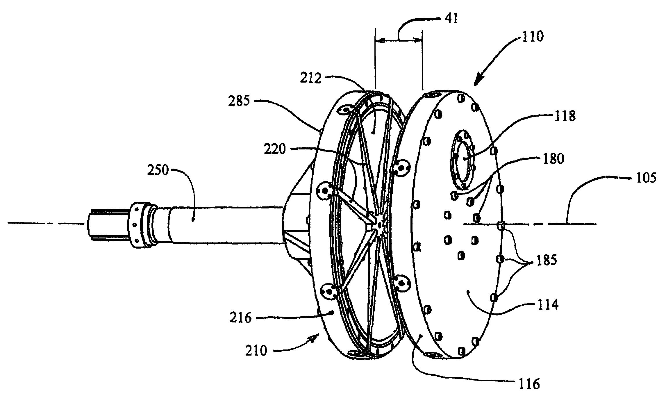
[0018]The present invention is also capable of operation in either rotational direction. Reversing the cutter head rotational direction exposes fresh cutting edges on the previously following edge of the cutting bars, effectively doubling the time between required blade maintenance. Still further time savings are realized through a novel means to retain the cutting bars in the cutting heads that enables the cutter bars to be removed and replaced in a short amount of time, typically one to two hours, without significant disassembly of the
machine. Removable cutting bars can be easily swapped for freshly sharpened cutter bars when cutting edges become worn. Receiving slots formed into the working surface of the cutting heads hold the cutting bars in position. Bolts securing the cutting bars in position are accessible from exterior portions of the cutter heads. These bolts prevent the cutter bars from sliding in or lifting out of the receiving slots while the invention is operating. Once removed, the bars may be flipped over to
expose two fresh cutting surfaces or replaced with a sharpened set of cutter bars. An additional benefit of the cutting bar retention method is that no fasteners are located within the working area of the apparatus where they might damage the cutting edges in the event they loosen and become entrained in the input material.
[0019]The invention also minimizes the power input requirement for the
machine to control capital and operating costs.
Cutting bars on opposing cutting heads interact as the cutting heads rotate relative to one another resulting in a shearing area between the cutting bars that comminutes the scrap tire material. Since the number of cutting bars on opposing cutting head differ by one, no more than one opposing pair of cutting bars will begin their shear interaction at any point in the cutting
head rotation. The rotating cutting heads cause the cutting bars interact in a manner where the shear point between the cutting bars moves outwardly along the cutting bar length as the cutting heads rotate, similar to the shearing action in a pair of scissors, so that the force encountered as material is initially sheared between the cutting bars is applied over the length of the cutting bar over a small interval of time rather than instantaneously would occur if the cutter bars interacted along their entire length at the same instant in time. The cutting bar arrangement also causes at least one pair of opposing cutting bars to interact at all times during cutting
head rotation. The shock loading and instantaneous
power demand are reduced to the level of input power needed to drive one cutting bar pair through the
shear zone. In contrast, if both cutting heads contained the same number of cutting bars, multiple pairs of cutting bars would begin shearing simultaneously. Additionally, the rotating cutting heads cause the cutting bars interact in a manner where the shear point moves outwardly along the cutting bar length as the cutting heads rotate, similar to the shearing action in a pair of scissors, so that the magnitude of the force created as material is sheared between the cutting bars is distributed over a small interval of time rather than instantaneously, further reducing stresses within the cutting bars. Lower stresses in the cutting bars allow them to remain sharper longer during operation and further contributes to the lower input power requirements for a given
crumb rubber output.
[0020]Lowering the input power also reduces the heat input to the process material. By reducing the power input requirements and lowering the
maximum temperature to which the process material is subjected,
machine operating costs are lowered, the risk of fire is lessened, and the machine is simplified by eliminating the need for an elaborate cooling
system for the process material while it is withing the working area of the cutting heads.

