Arrangement for and method of restricting the inflow of formation water to a well

a technology of formation water and inflow restriction, which is applied in the direction of wellbore/well accessories, sealing/packing, drilling pipes, etc., can solve the problems of reducing the control effect, and achieve the effect of reducing the flow, neutral buoyancy, and low mobility

Inactive Publication Date: 2007-03-06
HALLIBURTON ENERGY SERVICES INC
View PDF29 Cites 185 Cited by
  • Summary
  • Abstract
  • Description
  • Claims
  • Application Information

AI Technical Summary

Benefits of technology

[0007]The inflow of formation water from a well to a production tubing may be reduced by the hydrocarbon production in the well, e.g. within a 12 m long length of piping, flowing into one or more chambers connected to the production tubing. From the chamber, the oil flows on into the production tubing via a number of through nozzles in the tubing wall. A number of balls are disposed in the chamber. The balls have approximately the same density as the formation water. On production of oil, the balls will have a low mobility, as they have a density that is significantly higher than that of the oil; thus they will sink. The density of the oil is typically less than 900 kg/m3, while the water will have a density of approximately 1000 kg/m3. On partial production of water, these balls will have neutral buoyancy in the water and close nozzles thro...

Problems solved by technology

On production of oil, the balls will have a low mobility, as they have a density that is significantly higher than that of the oil; thus ...

Method used


Image

  • Arrangement for and method of restricting the inflow of formation water to a well
  • Arrangement for and method of restricting the inflow of formation water to a well

Examples


Embodiment Construction

[0014]For a clearer understanding of the invention, it will be described in the form of embodiments illustrated in the appended drawings, in which:

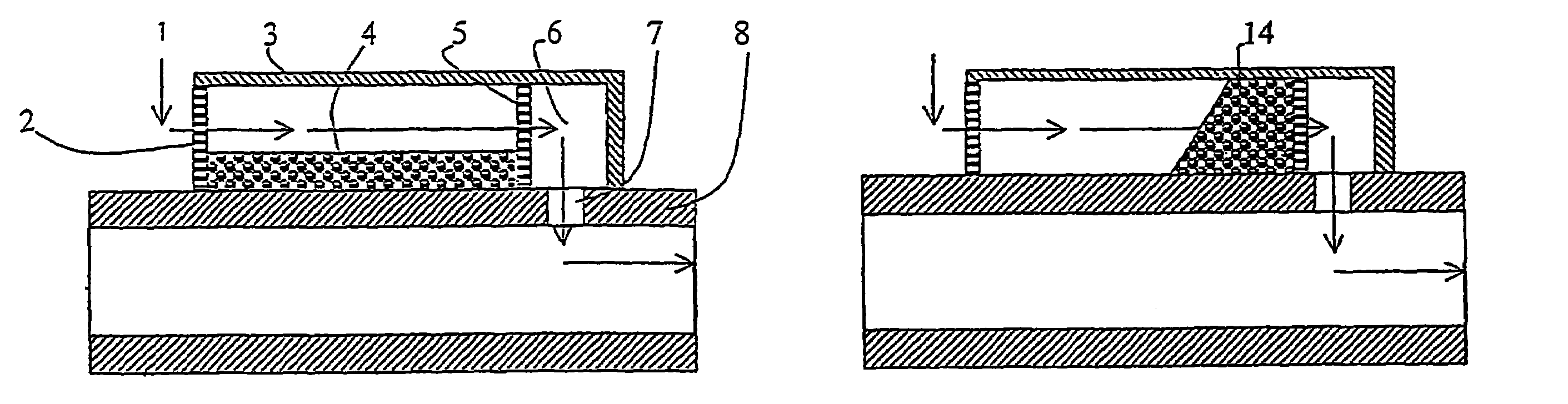
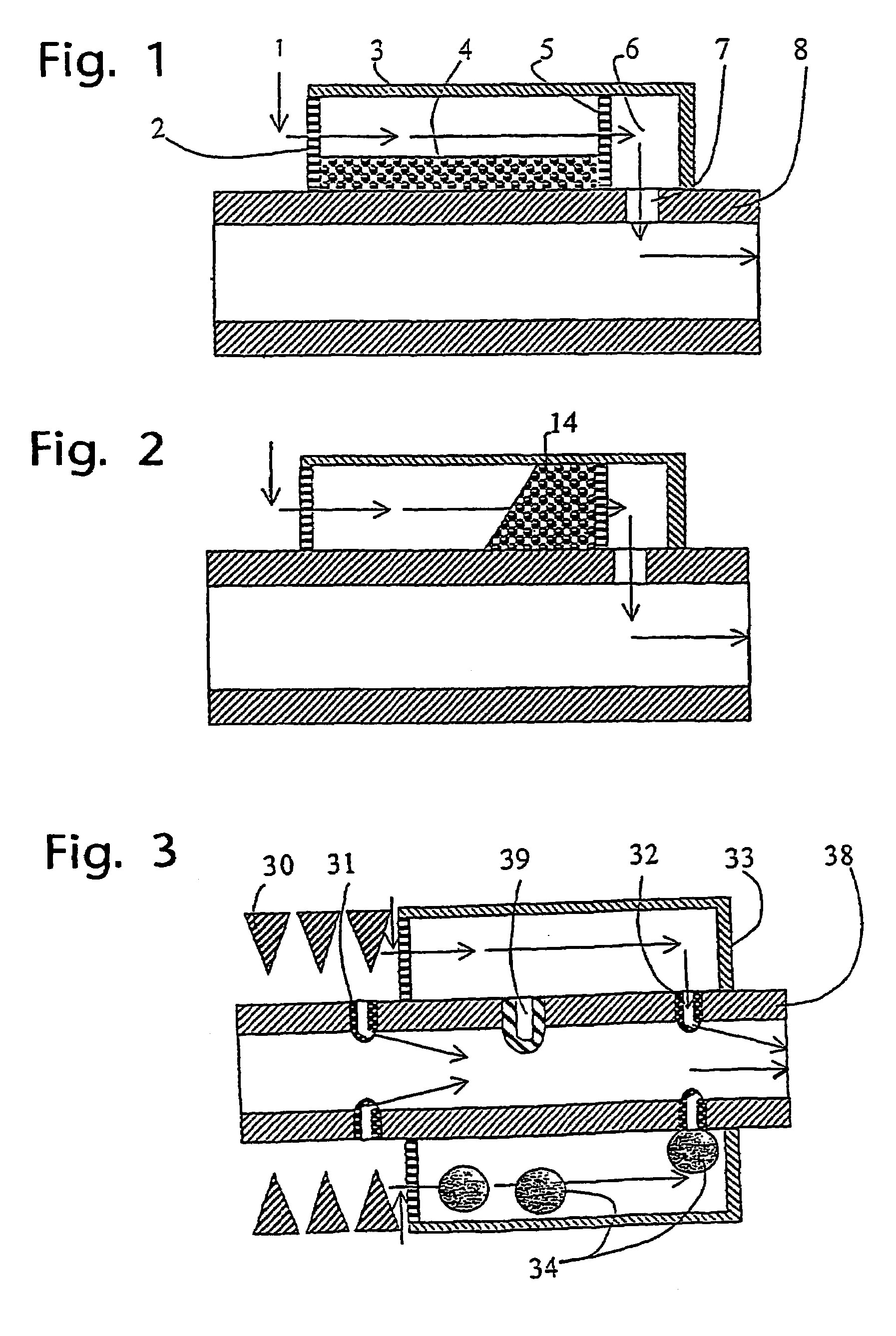
[0015]FIG. 1 shows a case where an oil stream 1 passes through a filter 2 and then into a flow chamber 3. A number of balls 4 are located at the lower side of this chamber due to the balls being heavier than the oil. The oil further flows through a filter 5 and into a space 6, in order to flow on through openings 7 and into the production tubing 8, then to follow the flow of oil up through the well.

[0016]FIG. 2 shows the same construction as FIG. 1, the difference being that here, water is flowing. The balls are now packed vertically, since the balls have neutral buoyancy. Thus is formed an aggregate 14 of balls causing a pressure drop in the flow.

[0017]FIG. 3 shows an annular sand filter 30, a bypass nozzle with a hole 31 in a production tubing 38, as well as an annular chamber 33 with balls 34, in which the balls 34 have approximately t...


PUM


Abstract

An arrangement for restricting the inflow of formation water from an underground formation to a hydrocarbon producing well, where, between the underground formation and a production tubing (38) located in the well, there is disposed at least one flow chamber (3, 33) connected to the production tubing (38), the flow chamber (3, 33), preferably via a filter (2) in one portion, being open to inflow of formation fluid and in communication with the production tubing (38) via at least one opening (7, 32), and where the flow chamber (3, 33) is provided with at least one free-floating body (4, 34) with approximately the same density as the formation water, the at least one body (4, 34) being designed by means of the closing of at least one opening (32) or choking, to reduce the inflow of formation water to the production tubing (38).

Description

CROSS REFERENCE TO RELATED APPLICATION[0001]The present application is the U.S. national stage application of International Application PCT / NO02 / 00158, filed Apr. 26, 2002, which international application was published on Nov. 14, 2002 as International Publication WO 02 / 090714. The International Application claims priority of Norwegian Patent Application 200012261, filed May 8, 2001.FIELD OF THE INVENTION[0002]This invention regards an arrangement for and a method of automatically controlling the inflow of formation water to a petroleum well by means of buoyancy elements.BACKGROUND OF THE INVENTION[0003]Oil and gas production will in most cases have to be stopped when the water production from a well becomes excessive. The time of water breakthrough will vary from one zone to the next, and will also depend on the measured depth of the zone due to flow pressure drop. If a zone that mainly has an inflow of water is choked, the production from zones producing mainly oil may be increase...

Claims


Application Information

Patent Timeline
IPC IPC(8): E21B43/12E21B34/08
CPCE21B43/12E21B43/08
Inventor FREYER, RUNE
Owner HALLIBURTON ENERGY SERVICES INC
Why Eureka
Try Eureka