
Method and apparatus for the continuous separation of biological fluids into components

a biological fluid and component technology, applied in the direction of separation process, hose connection, centrifuge, etc., can solve the problems of high manufacturing cost, less time-efficient process, high cost of manufacture, etc., to reduce the time necessary, improve the efficiency of current fluid separation process, and improve the effect of treating patients

Active Publication Date: 2007-03-06
MALLINCKRODT HOSPITAL PRODUCTS IP LTD
View PDF108 Cites 28 Cited by
  • Summary
  • Abstract
  • Description
  • Claims
  • Application Information

AI Technical Summary

Benefits of technology

"The present invention provides methods and apparatus for separating fluids, such as blood or other biological fluids, into their components. The invention aims to increase the efficiency of current fluid separation processes and decrease the time required for the process. The invention can be used in various applications, such as treating Graft-versus-Host disease, organ transplant rejection, and autoimmune diseases. The invention also allows for the continuous separation of fluid components without interrupting the process. Overall, the invention improves the efficiency and effectiveness of fluid separation processes."

Problems solved by technology

However, a major drawback to the Latham bowl separator is that the separation process must be repeatedly stopped to remove the packed RBCs and plasma once they fill the inside of the bowl, creating a “batch-type” process.
Although the Latham bowl separator has a high volume yield, the constant filling and emptying of this bowl wastes time; thus, the process is considered less efficient with respect to time.
Additionally, the Latham bowl requires a rotating seal, which is expensive and difficult to manufacture.
An additional drawback of centrifugal processing apparatus has been their high cost of manufacture due to strict tolerances, rotating seals, and extensive manufacturing processes.

Method used


Image

  • Method and apparatus for the continuous separation of biological fluids into components
  • Method and apparatus for the continuous separation of biological fluids into components
  • Method and apparatus for the continuous separation of biological fluids into components

Examples


Embodiment Construction

[0059]Reference will now be made in detail to the present preferred or exemplary embodiments of the invention, examples of which are illustrated in the accompanying drawings.

[0060]In a specific embodiment, the present invention relates to methods and apparatus that separate fluid components, such as, for example, the components of a biological fluid by density or weight. Biological fluids encompass fluids that comprise, exist in, or are used in, or delivered to living organisms. Indeed, biological fluids may comprise bodily fluids and their components, such as blood cells, plasma, and other fluids that comprise biological components, including living organisms such as bacteria, cells, or other cellular components. Biological fluids may also comprise whole blood or specific whole blood components, including red blood cells, platelets, white blood cells, and precursor cells. In particular, it may be desirable to remove blood from a patient for treatment, such as for example, extracorp...


PUM

PropertyMeasurementUnit
lengthaaaaaaaaaa
widthaaaaaaaaaa
heightaaaaaaaaaa

Abstract

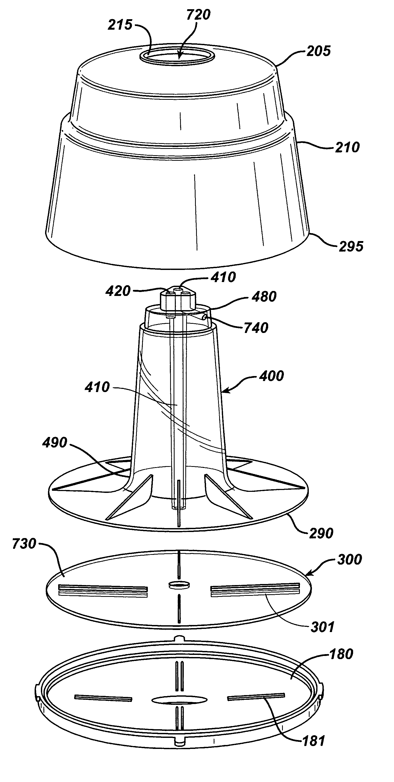
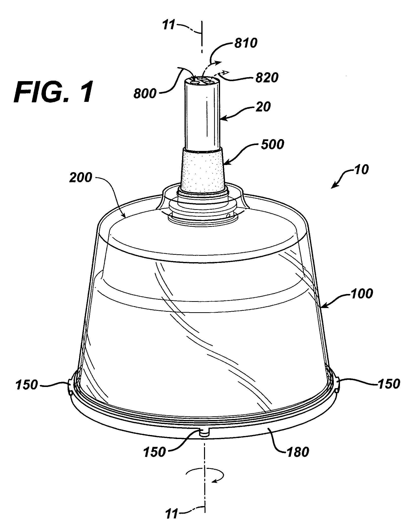
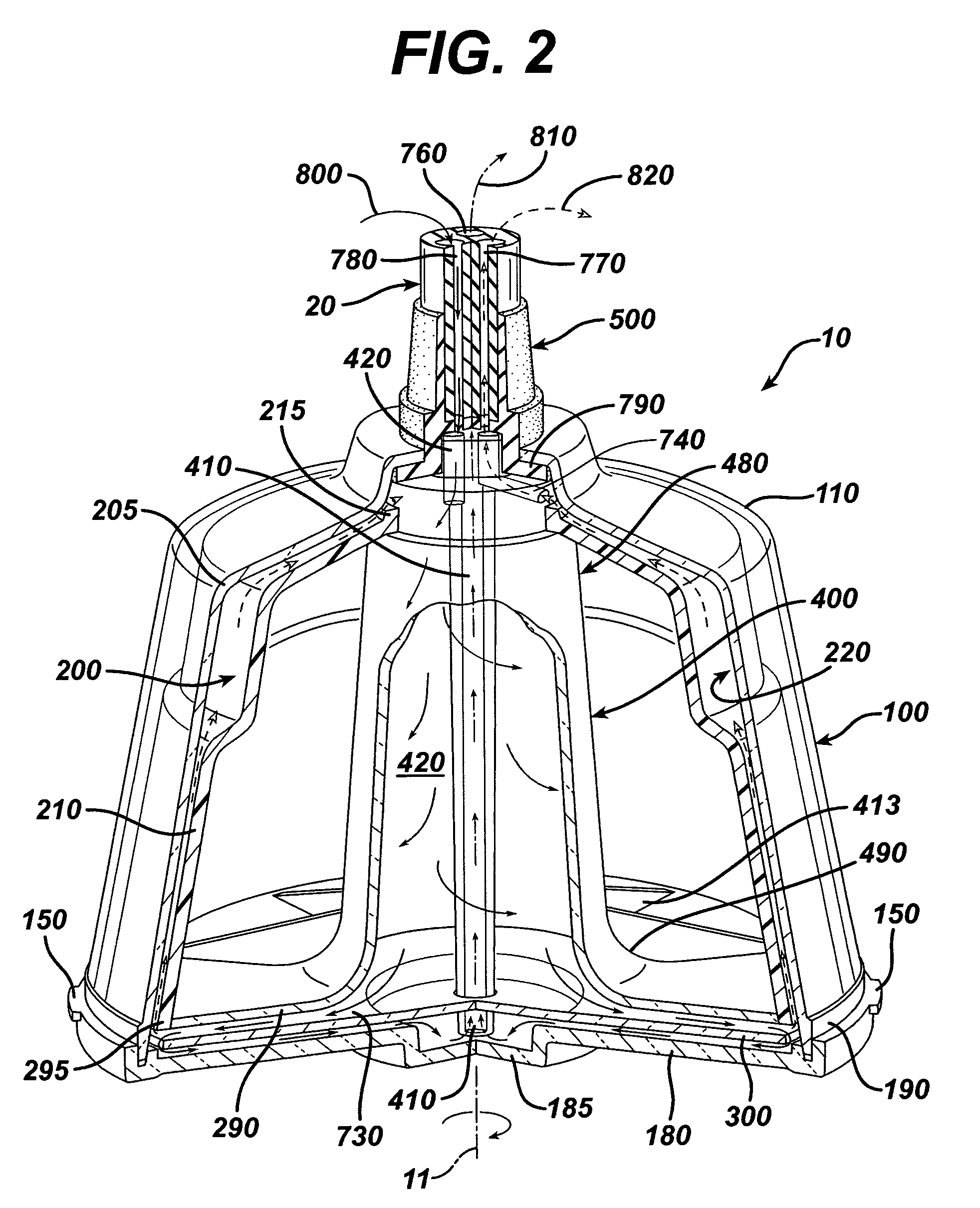
The present invention relates to systems, methods and apparatus for improving the yield for separating components of fluids, for example biological or sensitive fluids such as blood, and improving the component yield, for example, from donated whole blood by separating its components by density in a centrifuge bowl with a multi-axial lumen. The apparatus, system, and method eliminate the need to batch-type separate blood and can reduce the time needed to treat patients suffering from T-cell or white blood cell mediated diseases or conditions to less than 70 minutes. In one aspect, the invention is a centrifuge bowl (10) comprising an outer housing (100); a core (200); a lower plate (300); a lumen (400); a first bowl channel (420) within said lumen (400) for inflowing said fluid (800); a second bowl channel (410) for removing a first separated fluid component (810); and a third bowl channel (740) for removing a second separated fluid component (820).

Description

CROSS-REFERENCE TO RELATED APPLICATION[0001]This application claims the benefit of U.S. Provisional Application Ser. No. 60 / 361,287, filed Mar. 4, 2002.TECHNICAL FIELD OF THE INVENTION[0002]The present invention generally relates to methods and apparatus for separating a fluid into its components, for example, a biological or sensitive fluid such as blood, and specifically to methods and apparatus that use centrifugal force to separate a fluid into its components by density so as to improve the component yield.BACKGROUND ART[0003]With the advance of medical sciences, it has become possible to treat a patient's blood in closed-loop processes, returning the patient's own treated blood back to him in one medical treatment. An example of such processes include external treatment methods for diseases in which there is a pathological increase of lymphocytes, such as cutaneous T-cell lymphoma or other diseases affecting white blood cells. In such methods, the patient's blood is irradiated ...

Claims


Application Information

Patent Timeline
Patent Type & Authority Patents(United States)
IPC IPC(8): A61M37/00B01D33/15B04B1/00B04B9/12C02F1/38A61M1/36B04B5/04F16L33/00F16L39/02
CPCA61M1/3693A61M1/3696B04B5/0442A61M1/3681B04B2005/0464B04B2005/0492A61M2205/053A61M1/3683
Inventor BRIGGS, DENNIS A.HUTCHINSON, MICHAEL
Owner MALLINCKRODT HOSPITAL PRODUCTS IP LTD
Learn More