
Signal generation apparatus and method for seafloor electromagnetic exploration

Inactive Publication Date: 2007-03-06
OHM
View PDF14 Cites 27 Cited by
  • Summary
  • Abstract
  • Description
  • Claims
  • Application Information

AI Technical Summary

Benefits of technology

[0032]Accordingly the cycloconverter can prevent the switching being initiated by spurious zero crossings, while retaining the advantages of controlling the outgoing waveform by locking it to the phase and frequency of the ship-board power supply. The ship-board power supply can be controlled by a high quality and readily monitored frequency standard on the towing vessel.

Problems solved by technology

Whilst seismic surveying is able to identify such voids the technique is often unable to distinguish between the different possible contents within them, especially for void contents which have similar mechanical properties.
However, this is an expensive process, and one which provides no guarantee of reward.
Whilst the long wavelength signals which do penetrate to the sea-floor can be used for large scale undersea probing, they do not provide sufficient spatial resolution to examine the electrical properties of the typically relatively small scale subterranean reservoirs.
Accordingly, it is impossible to distinguish between a drift in the phase of the source signal and a change in the propagation time between source and receiver.
The precision to which the electrical properties of the rock strata, which determine the signal time delay, can be determined is therefore highly dependent on the stability of the source signal, the generation of which is not a straightforward task.
However, such an a.c. power source has significantly different characteristics from those desired for the outgoing waveform.
However, such an approach faces technical problems caused by the capacitive and inductive effects in the tow cable, the cycloconverter itself, and the dipole transmitting antenna, as now being explained.
Second, even if the power supply at the surface vessel is designed for low harmonic distortion, the input voltage and current waveforms at the deep-tow vessel are significantly affected by higher harmonics of the supply frequency and by standing waves set up in the system between the ship board power supply and the transmitting electrodes in the antenna.
The exact properties of these harmonics and standing waves are difficult to predict, and are likely to vary significantly between installations on different vessels, and even within a single deployment of the transmitter system as tow cable is paid out and hauled in.
If the zero crossings are used to control the switching of individual half sinusoids, and to control the timing of output waveform polarity reversals, then the source becomes subject to unpredictable frequency jitter and phase drift.

Method used


Image

  • Signal generation apparatus and method for seafloor electromagnetic exploration
  • Signal generation apparatus and method for seafloor electromagnetic exploration
  • Signal generation apparatus and method for seafloor electromagnetic exploration

Examples


Embodiment Construction

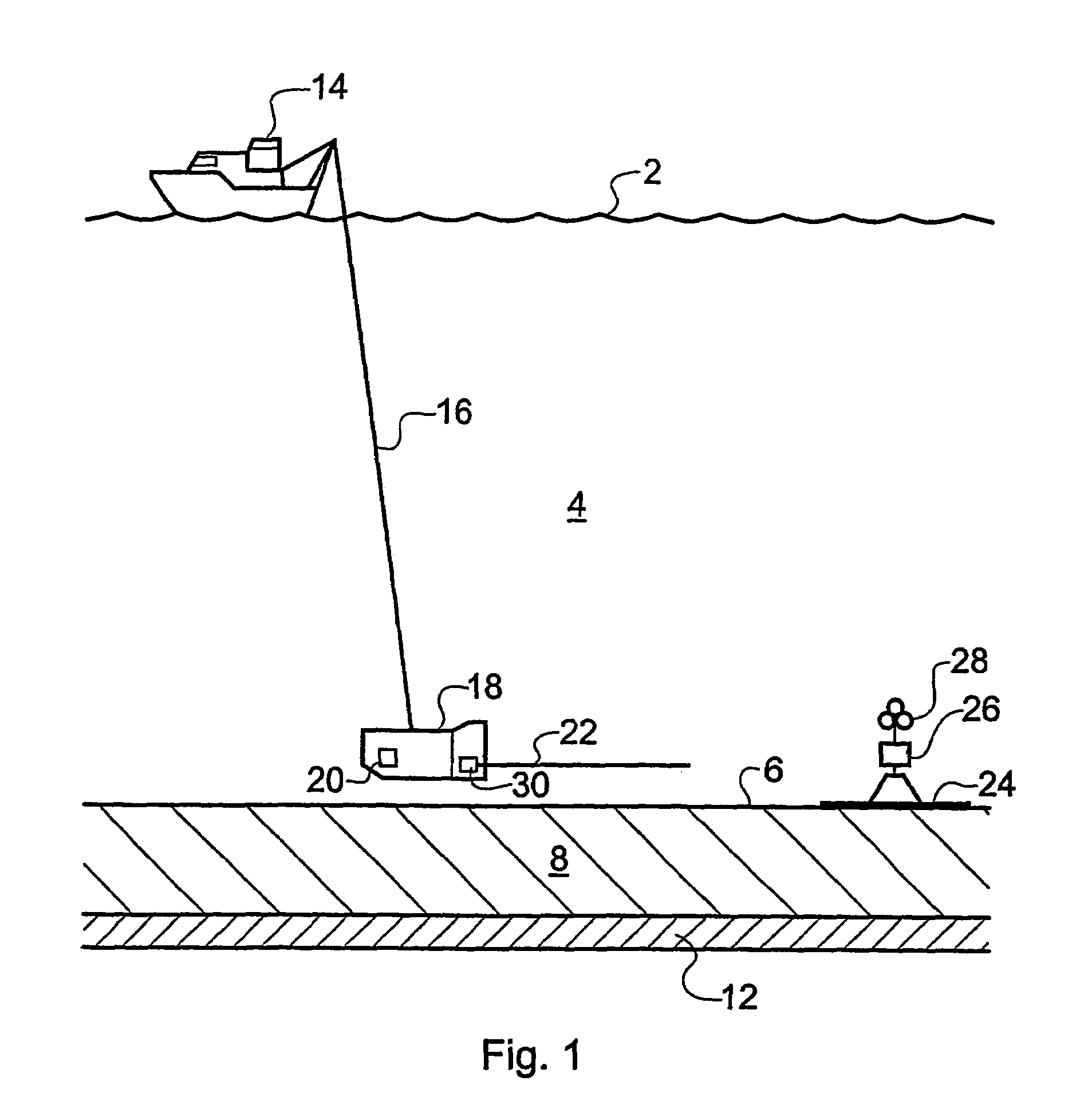
[0043]An embodiment of the invention is now described. The embodiment conforms to the general description associated with FIGS. 1 and 2. The foregoing description of those figures is not repeated for the sake of brevity. The following description confines itself to a description of the design of the cycloconverter unit.

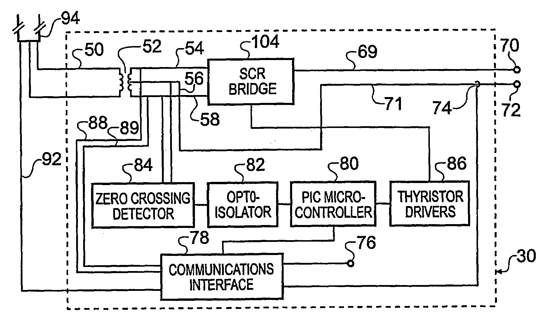
[0044]FIG. 6 is a schematic block diagram of the cycloconverter unit 30 according to an embodiment of the invention. Power and communication cables 50, 92 are carried to the cycloconverter unit 30 via the umbilical connection 94 which connects to the surface vessel 14. The cycloconverter is housed in a pressure container (not shown) in the deep-towed vehicle 18. The waveform generated by the power supply in the surface vessel is in this example sinusoidal with a stabilised frequency of 256 Hz, an amplitude of 2550 V. The signal may be up to 5 Amperes with the example power supply. A 43:1 step down transformer 98 has a plurality of tappings on its secondary windings to...


PUM


Abstract

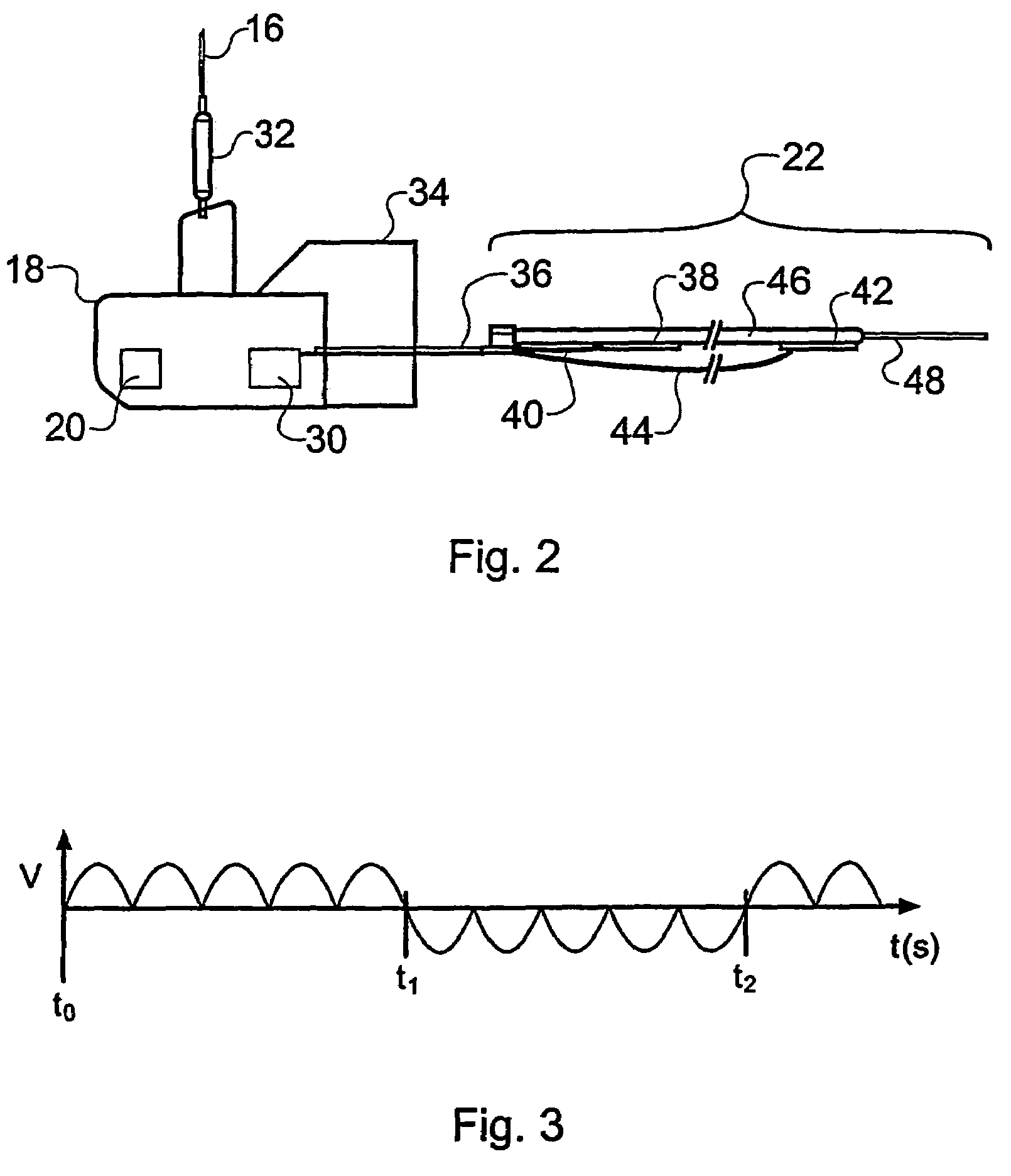
An apparatus for generating electronic signals for application in subsea electromagnetic exploration. A surface generated high-voltage low-current source signal stabilized at a first frequency is supplied to a deep-tow vehicle (18) via an umbilical cable (16). The high-voltage low-current signal is transformed at the deep-tow vehicle to a high-current low-voltage a.c. signal by a transformer (52) within a cycloconverter (30). A semiconductor relay bridge (104) provides switchable rectification of the high-current low-voltage a.c. signal to provide a quasi-square wave at a second frequency, lower than the first frequency, for supply to a transmitting antenna (22) towed by the deep-tow vehicle. The times of the rectification switching are dependent on zero crossings of the high-current low-voltage a.c. signal. Allowable rectification switching times may be gated to occur only within pre-determined time windows to avoid noise-induced zero-crossing switching. The apparatus allows multiple transmission frequencies to be derived from a single stabilized source and improves spectral integrity by avoiding rectification switching at zero-crossings not occurring at the first frequency.

Description

[0001]This application is a national phase of International Application No. PCT / GB02 / 04460 filed Oct. 2, 2002 and published in the English language.BACKGROUND OF THE INVENTION[0002]The invention relates to an apparatus and method for generating electronic signals for use in the field of seafloor electromagnetic exploration.[0003]Determining the response of the sub-surface strata within the earth's crust to electromagnetic fields is a valuable tool in the field of geophysical research. The geological processes occurring in thermally, hydrothermally or magmatically active regions can be studied, for example. In addition, electromagnetic sounding techniques can provide valuable insights in to the nature, and particularly the likely hydrocarbon content, of subterranean reservoirs in the context of subterranean oil exploration and surveying.[0004]Seismic techniques are often used during oil-exploration expeditions to identify the existence, location and extent of reservoirs in subterrane...

Claims


Application Information

Patent Timeline
IPC IPC(8): H02M7/505G01V3/12H02M5/257H02M5/27
CPCG01V3/12H02M5/27H02M5/2573
Inventor SINHA, MARTIN C.MACGREGOR, LUCY M.
Owner OHM
Learn More