
Low emission energy source

a low-emission energy source and low-emission technology, applied in the ignition of turbine/propulsion engines, engine starters, lighting and heating apparatus, etc., can solve the problem of reducing the generating capacity, and reducing the occurrence of greenhouse gasses

Inactive Publication Date: 2007-03-20
BRIGHTSOURCE ENERGY
View PDF11 Cites 72 Cited by
  • Summary
  • Abstract
  • Description
  • Claims
  • Application Information

AI Technical Summary

Problems solved by technology

The difference between actual energy recovered and potential energy available, i.e., the 70% to 40% loss in efficiency, is a result of several factors, including inadequate or incomplete combustion of the fuel, generation of wasted heat, frictional losses in the mechanisms used to transform the chemical energy released in combustion to physical energy in the output shaft, exhausting of the combusted mixture before complete recovery of the energy thereof, etc.
Each of these factors adds to yield a relatively inefficient internal combustion engine.
However, gas turbines as a primary engine and without a method of secondary heat recovery are less efficient than diesel cycle engines, which are currently, on a stand alone basis (i.e., no secondary heat recovery based power generation) the most efficient engines commercially available.
Further, engines operating on the Stirling cycle would theoretically be more efficient, but have never gained commercial acceptance.
The relatively efficient diesel engine using commercial fuels has an exhaust temperature insufficient for efficient steam turbine power generation therewith, whereas the gas turbine has high enough combustion temperature, and exhaust temperature, to allow sufficient heat recovery for commercial uses.
However, the engine also released, as exhaust, unacceptably rich emissions of greenhouse gasses as nitrogen oxides, approximately double that of a non-oxygen enriched diesel cycle engine, and also was unable to be effectively controlled.
As a result, this concept has not been further pursued.
An ongoing issue with the use of fossil fuels or other hydrocarbons in conjunction with internal combustion engines is the generation of pollutants, such as NOx or COx compounds.
A portion of these emissions, specifically the NOx compounds, are known to cause disruption of the ozone layer, and / or smog, as well as being generally unhealthy when inhaled.
CO is toxic, as is an additional emission gas, CHx, Likewise, CO2 has been implicated in global warming, and the emission of it may become limited in the future.
Thus, although the efficiency of the engine can be increased, the resulting pollution is unacceptable.
Further, these peak plants are often operated only during peak demand periods, and thus their cost, i.e., the investment in infrastructure, is not recoverable based upon continuous generation, but rather based on less that full utilization.
Although SEGS have proven to be capable of providing power during peak operation times, there are limits of competitiveness which affect their use for base line power generation needs.
As the plants cannot operate in non-daylight hours, the cost of building the solar power generation equipment must be justified based solely upon generation during these daylight hours.
However, because of the limitations on the use of fossil fuels and the requirement that the plant must be able to produce 100% of its rated output from solar alone to receive preferential supply status and certain tax and other benefits of being considered solar, the fossil fuel based generation is minimally used and sub-optimum power generation equipment is used.
For example, although it may be reasonable to combine gas turbine and solar generation, the cost effective solar plants available before this new technology are not able to produce for technical reasons the full rated power of the plant from solar alone.
Thus a current SEGS plant cannot operate highly efficient combined gas-steam cycle turbines and still be considered a solar plant in many if not all locales.
However for many reasons most of which can ultimately be related to lack of sufficient material technology at this stage this approach is too expensive, inefficient and unreliable to be developed in to a commercial product.

Method used


Image

  • Low emission energy source
  • Low emission energy source
  • Low emission energy source

Examples


Embodiment Construction

[0030]So that the manner in which the above recited features of the present invention can be understood in detail, a more particular description of the invention, briefly summarized above, may be had by reference to embodiments, some of which are illustrated in the appended drawings. It is to be noted, however, that the appended drawings illustrate only typical embodiments of this invention and are therefore not to be considered limiting of its scope, for the invention may admit to other equally effective embodiments.

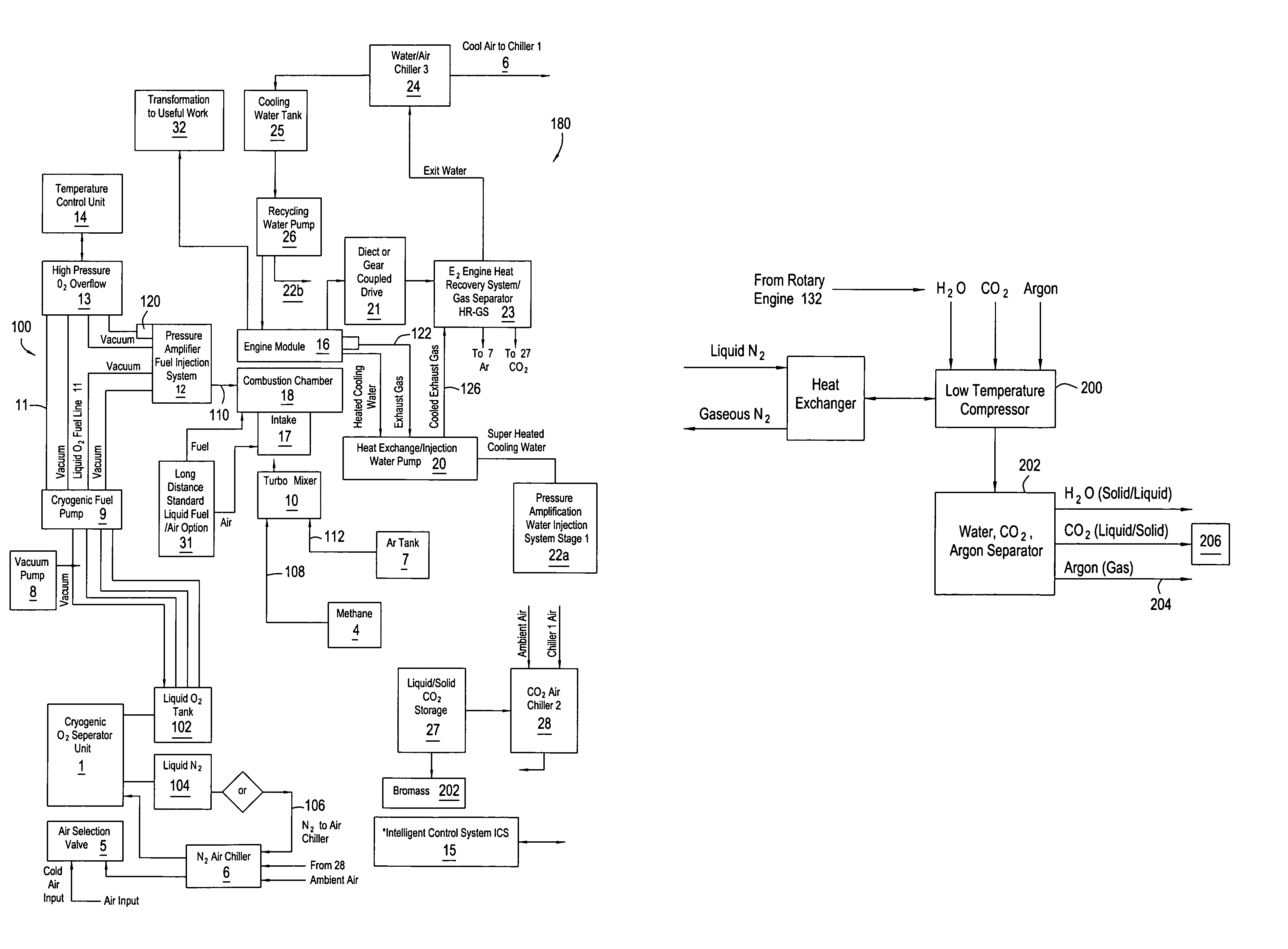
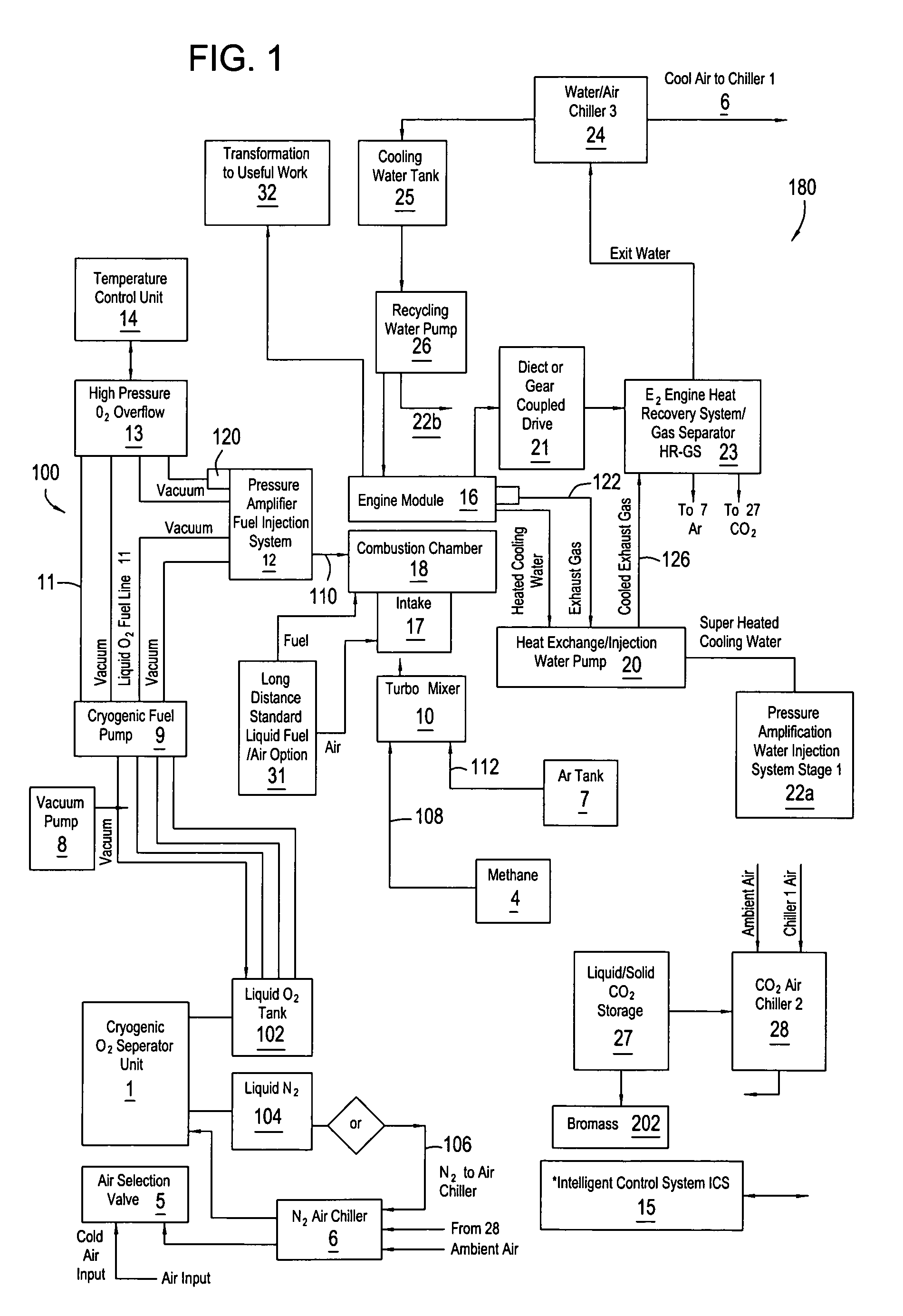
[0031]FIG. 1 is a schematic representation of an embodiment of the power generator of the present invention, showing the individual components and their interconnection useful for generating power with minimal emission and a relatively high efficiency. Essentially, in this embodiment, the major components of the invention include an internal combustion engine 16, such as a diesel cycle engine, an engine heat recovery and gas separator system 23 for the separation of the...


PUM


Abstract

A power generator provides power with minimal CO2, NOx, CO, CH4, and particulate emissions and substantially greater efficiency as compared to traditional power generation techniques. Specifically nitrogen is removed from the combustion cycle, either being replaced by a noble gas as a working gas in a combustion engine. The noble gas is supplemented with oxygen and fuel, to provide a combustion environment substantially free of nitrogen or alternatively working in 100% oxygen-fuel combustion environments. Upon combustion, Very little to no nitrogen is present, and thus there is little production of NOx compounds. Additionally, the exhaust constituents are used in the production of power through work exerted upon expansion of the exhaust products, and the exhaust products are separated into their constituents of noble gas, water and carbon dioxide. The carbon dioxide may be used in conjunction with a biomass to accelerate the biomass growth and to recover the oxygen enriched air resulting from algae photosynthesis for enhancing the operation of the power generator using the as Biomass for processing into methanol / ethanol and biological oils as fuel for the power generator. The biomass fuel is seen as a solar fuel and may be used in conjunctions with other solar fuels like heated thermal oil and others, as well as clean fossil fuels to optimize to clean, and efficient operation of the power generator in various regulatory contexts.

Description

CROSS-REFERENCE TO RELATED APPLICATIONS[0001]This application claims benefit of U.S. provisional patent application Ser. No. 60 / 441,088, filed Jan. 21, 2003 which is herein incorporated by reference.BACKGROUND OF THE INVENTION[0002]1. Field of the Invention[0003]Embodiments of the present invention generally relate to power generation, more particularly power generation incorporating combustion, such as internal combustion engines, including power generation wherein it is desirable to reduce the emission of oxides of nitrogen, hydrocarbons, carbon dioxide and particulates. More particularly still, embodiments of the invention include power generation using a power source having a regeneration mechanism, whereby emissions from combustion are recovered for reuse as a source of fuel for the power source. Additionally, the power generation methods and apparatus herein may be used to provide solar generation capability.[0004]2. Description of the Related Art[0005]Power generation employi...

Claims


Application Information

Patent Timeline
Patent Type & Authority Patents(United States)
IPC IPC(8): F02B47/06F02B43/12F02D23/00F02M25/06F02C7/22F02B43/02F02B47/02F02D19/12F02M25/00F03G6/00
CPCF02B43/02F02B47/02F02D19/12F02M25/00F02M25/0222F03G6/00Y02E10/46Y02T10/121Y02T10/32F25J3/04072F25J3/04157F25J3/0426F25J3/04563F25J2205/20F25J2210/80F25J2230/08F25J2230/80F25J2235/50F25J2260/44F25J2260/58F25J2260/80Y02T10/12Y02T10/30
Inventor GOLDMAN, ARNOLD J.
Owner BRIGHTSOURCE ENERGY
Learn More