
Method for forming a silicon oxide layer using spin-on glass

a technology of silicon oxide and spin-on glass, which is applied in the direction of semiconductor/solid-state device manufacturing, basic electric elements, electric devices, etc., can solve the problems of uneven surface of the first insulating layer formed over those elements, metal layer may exhibit various defects, and uneven surface of the top layer

Active Publication Date: 2007-03-20
SAMSUNG ELECTRONICS CO LTD
View PDF15 Cites 29 Cited by
  • Summary
  • Abstract
  • Description
  • Claims
  • Application Information

AI Technical Summary

Benefits of technology

The present invention provides methods for making silicon oxide layers during semiconductor device processing. These methods involve curing a layer of SOG (silicon oxide gas) using an oxidant solution and thermal treatments to convert it into silicon oxide. The oxidant solution can contain various oxidants such as ozone, peroxides, permanganates, hypochlorites, chlorites, chlorates, perchlorates, hypobromites, bromites, bromates, hypoiodites, iodites, iodates, and strong acids. The concentration of oxidant in the solution can range from 1 ppm to 40 wt % and the temperature can range from 5°C to 125°C. The oxidant solution can be applied to the SOG layer using dipping, immersion, spray, or puddle techniques. The technical effect of this invention is to provide a reliable and efficient method for making silicon oxide layers during semiconductor device processing.

Problems solved by technology

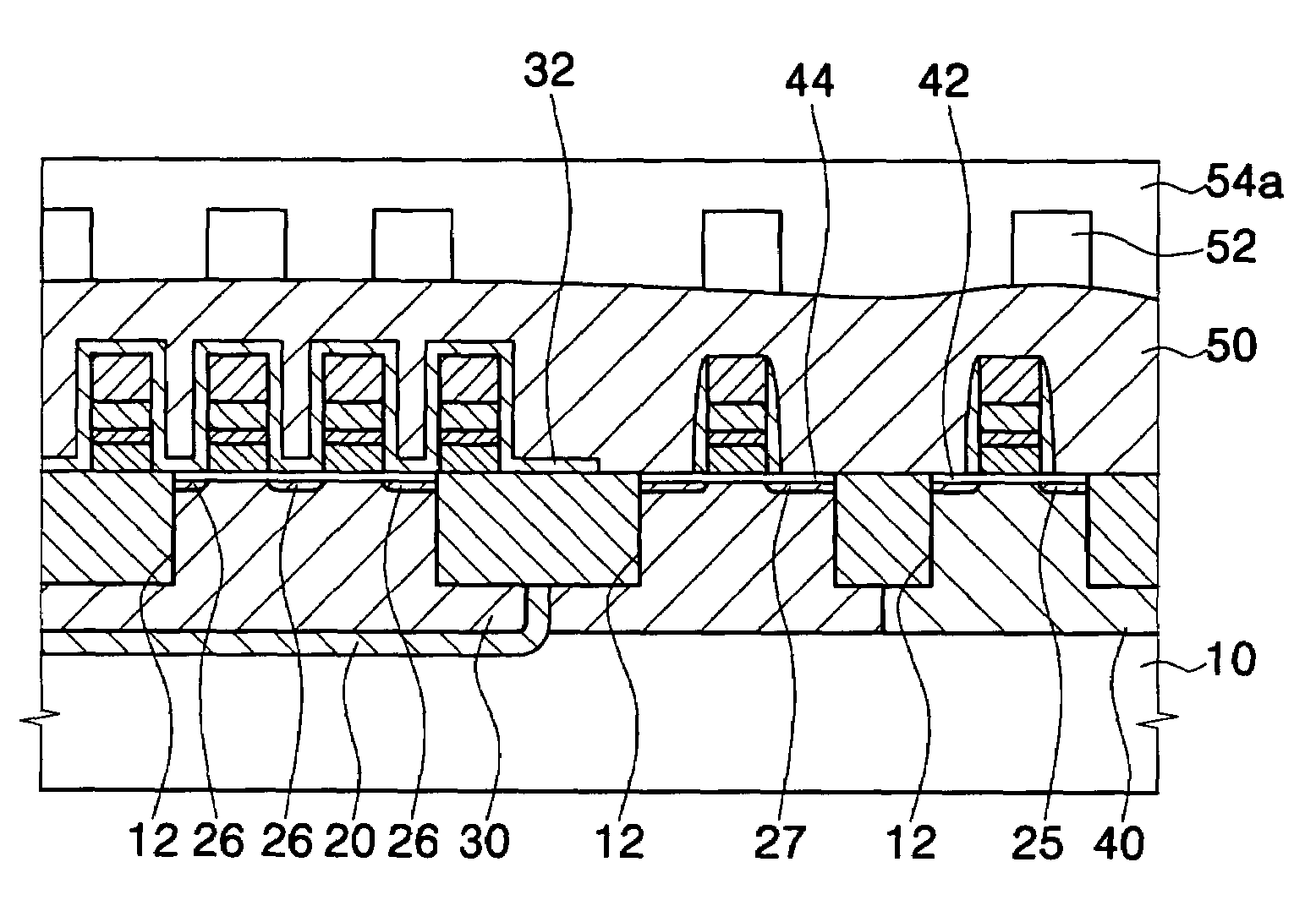
During the process of forming such multilevel interconnection structures, the surface of the top layer tends to become increasingly irregular and uneven as the circuit elements and interconnection patterns are formed.
Because the circuit elements tend to present an uneven surface topography, the surface of the first insulating layer formed over those elements will also tend to be uneven.
If the first metal layer is formed directly on an uneven first insulation layer, however, the metal layer may tend to exhibit various defects such as thinning or fractures as a result of protrusions and openings present in the underlying insulation layer.
If a second metal layer is formed directly on an uneven insulating layer, the second metal layer may also tend to exhibit various defects such as thinning or fractures as a result of the varied topography of the underlying insulation layer.
Because defects in any of the metal patterns will tend to depress both the yield and the reliability of the resulting semiconductor devices, conventional semiconductor processes tend to include planarization steps to produce a relatively planar surface on the insulting layer before forming the contact or via openings or depositing the conductive layers.
However, these types of oxide layers tend to exhibit poor gap-filling characteristics, e.g., a layer having bridges, gaps and voids, when the structures being coated have feature sizes consistent with design rules such as those for 0.13 μm and sub-0.10 μm devices.
In addition, gases used in the BPSG deposition process are expensive and severely toxic and, once deposited, the BPSG layer requires a high-temperature reflow process to achieve a more planarized surface.
Further, compared with other oxides, BPSG tends to exhibit a higher etch rate in wet etchants, such as HF or BHF solutions, thereby complicating control of the etch process.
As the device packing density increases and the design rule sizing decreases for memory devices having capacities on the order of 256 megabits or more, BPSG insulation layers may tend to exhibit increased numbers of defects, such as voids and bridges, that tend to reduce device yield and reliability.
Further, although an etch stop layer may be used to address etch selectivity issues, the formation of the BPSG layer may damage the etch stop layer and the additional layer results in increased process complexity.
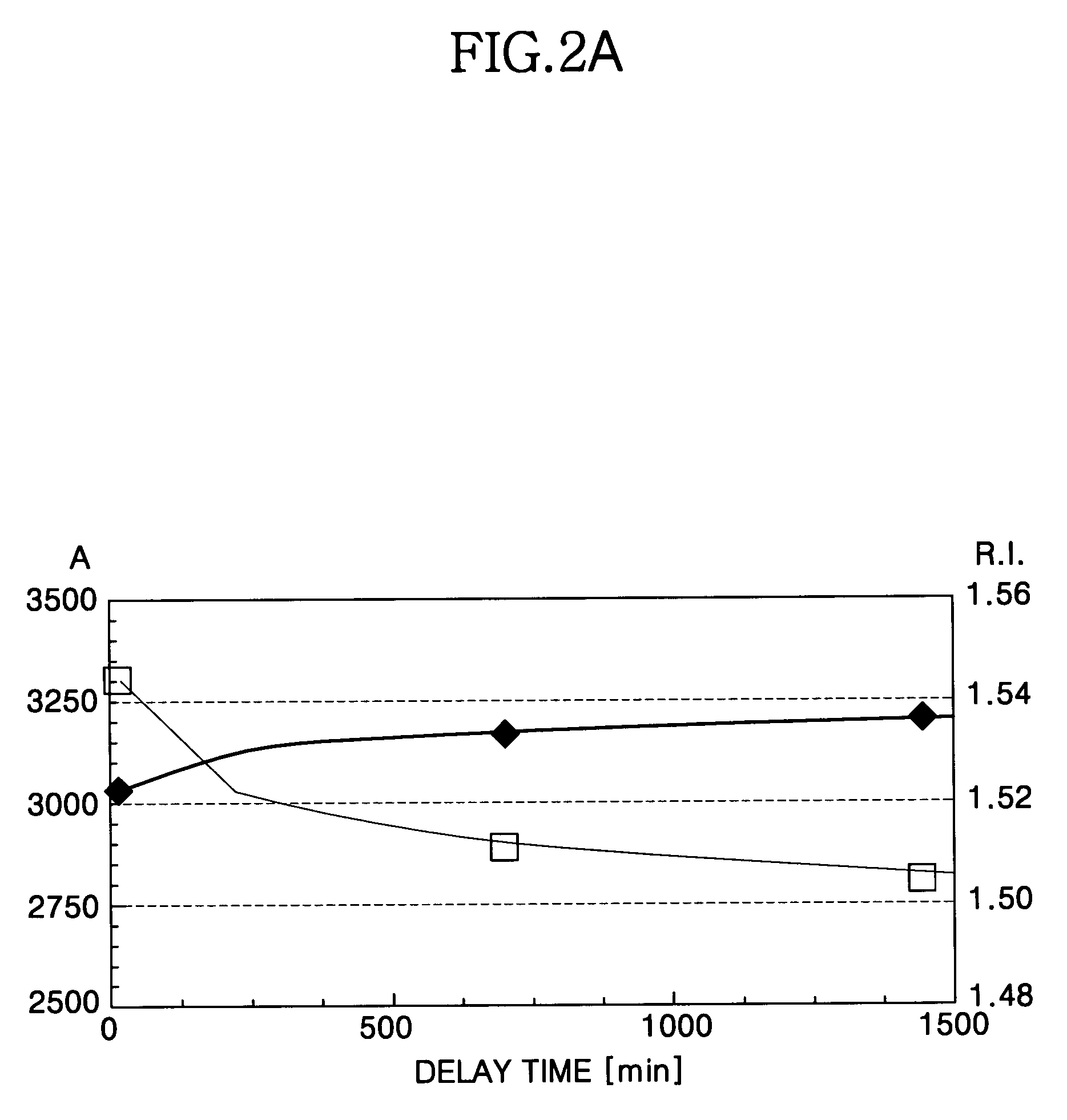
2A–B and 3A–B, the R.I., thickness and etch rate of the SOG layer vary over time, thus complicating efforts to control the SOG etch process and increasing the chance of overetching or underetching such a SOG layer.
Aging in oxidizing atmosphere may prevent such problems, but the aging takes long time to delay manufacturing process.

Method used


Image

  • Method for forming a silicon oxide layer using spin-on glass
  • Method for forming a silicon oxide layer using spin-on glass
  • Method for forming a silicon oxide layer using spin-on glass

Examples


experiment 1

[0067]A SOG composition including polysilazane according to an exemplary embodiment of the invention was spin coated onto a bare test wafer to form a SOG layer of about 3,400 Å. This SOG layer was then hard-baked at about 400° C. for about 30 minutes, and then cured by immersion in an oxidant solution according to an exemplary embodiment of the invention for about ten minutes, thereby substantially converting the SOG layer into a silicon oxide layer. After measuring the thickness of the resulting silicon oxide layer, the test wafers were wet etched for 20 seconds in a 25° C. aqueous solution of buffered oxide etchant (NH4F+HF buffered solution). The thickness of the remaining silicon oxide layer was then measured and subtracted from the initial measurement to determine the amount removed. The amount removed during the etch was determined to be about 1570 Å.

experiment 2

[0068]Test wafers having silicon oxide layers were prepared according to the procedure described above with regard to Experiment 1. The test wafers were then held under ambient conditions for one day after converting the SOG layer into the silicon oxide layer. After the hold period was completed, the test wafers were etched as described with regard to Experiment 1 and the amount removed during the etch was determined to be about 1530 Å.

experiment 3

[0069]Test wafers having silicon oxide layers were prepared according to the procedure described above with regard to Experiment 1. The test wafers were then held under ambient conditions for two days after converting the SOG layer into the silicon oxide layer. After the hold period was completed, the test wafers were etched as described with regard to Experiment 1 and the amount removed during the etch was determined to be about 1520 Å.


PUM

PropertyMeasurementUnit
temperatureaaaaaaaaaa

Abstract

A method is provided for forming silicon oxide layers during the processing of semiconductor devices by applying a SOG layer including polysilazane to a substrate and then substantially converting the SOG layer to a silicon oxide layer using an oxidant solution. The oxidant solution may include one or more oxidants including, for example, ozone, peroxides, permanganates, hypochlorites, chlorites, chlorates, perchlorates, hypobromites, bromites, bromates, hypoiodites, iodites, iodates and strong acids.

Description

BACKGROUND OF THE INVENTION[0001]1. Field of the Invention[0002]The present invention relates generally to a method for curing a spin-on glass (SOG) composition including polysilazane to form silicon oxide and, more particularly, to a method for curing a SOG layer with an oxidant solution to form a silicon oxide layer during the manufacture of the semiconductor device.[0003]2. Description of the Related Art[0004]The design and manufacture of semiconductor devices continues to improve and produce semiconductor devices having higher operating speeds and larger storage capacities. In order to expand upon the current generation of semiconductor devices, efforts are continuing to develop improved designs and processes for increasing density, improving reliability, reducing cost and / or reducing response time.[0005]Integrated circuits are typically manufactured by forming large numbers of transistors, capacitors and other circuit elements on a single substrate. The various transistors and ...

Claims


Application Information

Patent Timeline
Patent Type & Authority Patents(United States)
IPC IPC(8): H01L21/31H01L21/461H01L21/312H01L21/314H01L21/316H01L21/762H01L21/768
CPCH01L21/02164H01L21/02222H01L21/02282H01L21/02326H01L21/76828H01L21/3125H01L21/3165H01L21/76229H01L21/76826H01L21/02343H01L21/02129
Inventor GOO, JU-SEONHONG, EUN-KEEKIM, HONG-GUNNA, KYU-TAE
Owner SAMSUNG ELECTRONICS CO LTD
Learn More