
Variable speed motor

a variable speed motor and speed technology, applied in the direction of motor/generator/converter stopper, motor/dynamo-electric converter control, motor/dynamo-electric converter starter, etc., can solve the problems of greatly reducing the efficiency of motors, and greatly increasing the production cost of variable speed motors. , the effect of reducing the air gap flux density and reducing the production cost of variable speed motors

Active Publication Date: 2007-03-27
LG ELECTRONICS INC
View PDF17 Cites 14 Cited by
  • Summary
  • Abstract
  • Description
  • Claims
  • Application Information

AI Technical Summary

Benefits of technology

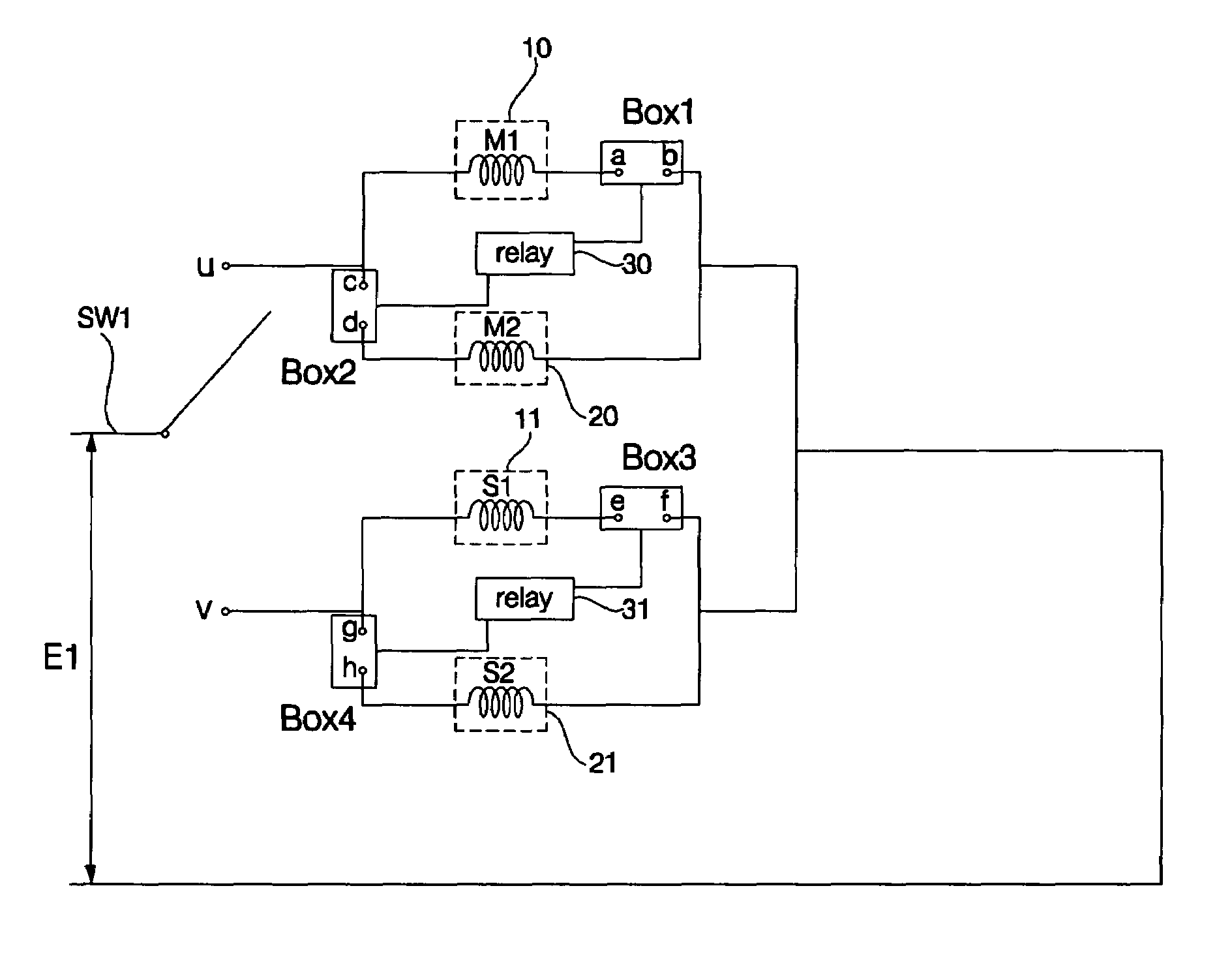
The present invention provides a variable speed motor that can control motor speed without using a drive unit capable of performing a speed variation function at an external location. This reduces production costs, reduces electromagnetic vibration noise, and reduces power consumption. The motor includes a plurality of main windings wound on a stator to form a plurality of poles, and a relay for performing a switching operation between serial / parallel connections of the main windings. The motor also includes an auxiliary winding and at least one capacitor unit additionally connected in parallel to the auxiliary winding, and a capacitor control circuit for controlling capacitances and input voltages of individual capacitors contained in the capacitor unit. The motor can control the motor speed in multiple stages using the tap winding and the high-speed or low-speed dehydration process can be changed in multiple stages to prevent damage to laundry and reduce power consumption.

Problems solved by technology

In this case, the cost of production is greatly increased, so that the cost of production of a variable speed motor is also greatly increased.
However, the above-mentioned pole-change single-phase induction motor uses four windings to perform a pole-change operation, a cross-sectional area of a slot is increased, efficiency of the motor is greatly reduced by the increased core loss of the stator, and a minimum variable speed which can be implemented is also limited, such that it has difficulty in extending the range of a variable speed.

Method used


Image

  • Variable speed motor
  • Variable speed motor
  • Variable speed motor

Examples


Embodiment Construction

[0044]Now, preferred embodiments of the present invention will be described in detail with reference to the annexed drawings. In the drawings, the same or similar elements are denoted by the same reference numerals even though they are depicted in different drawings. In the following description, a detailed description of known functions and configurations incorporated herein will be omitted when it may make the subject matter of the present invention rather unclear.

[0045]A preferred embodiment of the variable speed motor according to the present invention will hereinafter be described with reference to the annexed drawings.

[0046]A variable speed motor according to the present invention is a single-phase induction motor to which a single-phase AC power signal is applied. In the case of an outer-rotation motor in which a rotor is mounted to the outside of a stator, a rotation radius of the outer-rotation motor is greater than that of an inner-rotation motor, and torque per unit volum...


PUM


Abstract

A variable speed motor includes first and second main windings wound on a stator, and a relay for performing a switching operation between serial / parallel connections of the first and second main windings to control motor speed. The variable speed motor further includes a tap winding connected in series to the main windings, or an additional capacitor, such that it can greatly extend the range of a variable speed without using a drive unit capable of changing the motor speed at an external location, resulting in reduced production costs of the motor, reduced electromagnetic vibration noise, and reduced power consumption.

Description

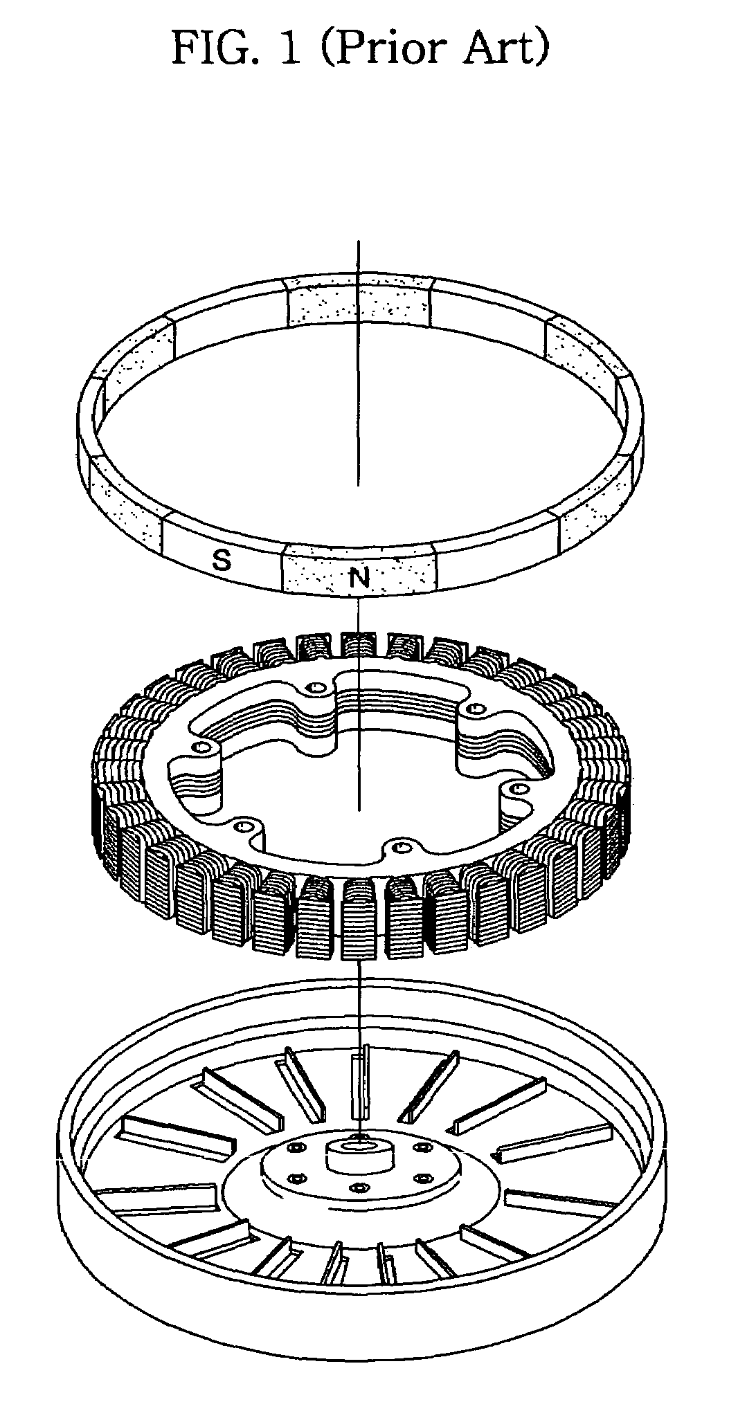
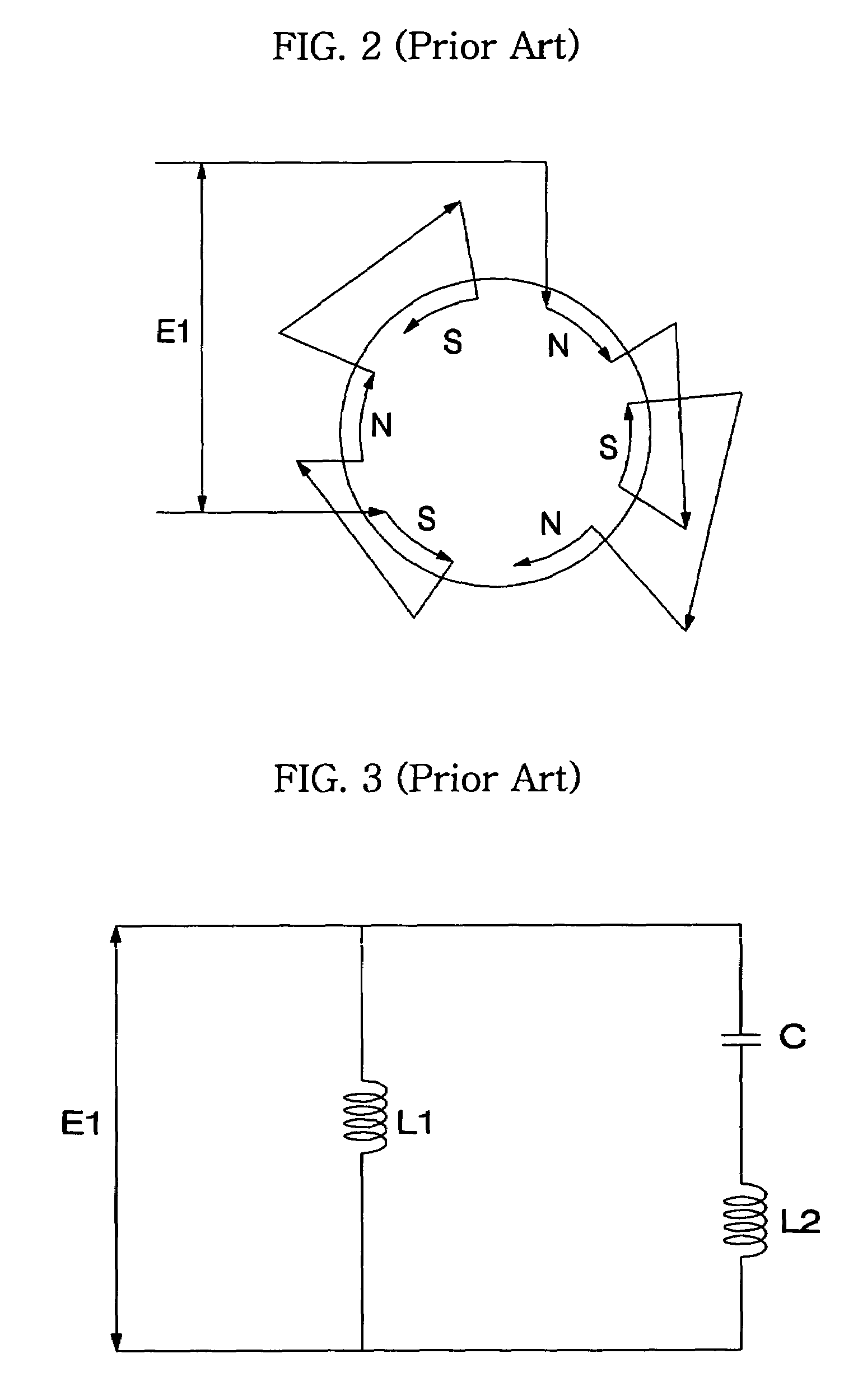
BACKGROUND OF THE INVENTION[0001]1. Field of the Invention[0002]The present invention relates to a variable speed motor, and more particularly to a variable speed motor for use in a motor capable of receiving single-phase Alternating Current (AC) power, which includes windings mounted to a stator of the motor to form poles, and a relay for connecting the windings in series or in parallel to each other to control speed of the motor, such that it can properly vary a rotation speed of the motor.[0003]2. Description of the Related Art[0004]FIG. 1 is an exploded perspective view of a rotor and a stator contained in a conventional outer-rotation motor. FIG. 2 is a motor winding arrangement illustrating a layout of a conventional 6-pole winding.[0005]Typically, a motor includes a stator to which windings are mounted, a permanent magnet, and a rotator formed of an Al (aluminum) conductor or iron core. The motor generates periodic current variation in the winding mounted to the stator, torqu...

Claims


Application Information

Patent Timeline
Patent Type & Authority Patents(United States)
IPC IPC(8): H02P1/44H02P25/04H02P27/06
CPCH02P25/04
Inventor KIM, DONG WONMIN, BYOUNG WOOKCHOI, BYUNG KEOLLEE, TAE HEE
Owner LG ELECTRONICS INC
Learn More