
Manifold array processor

a multi-layer array and processor technology, applied in the field of parallel processing architectures, can solve the problems of consuming a great deal of valuable integrated circuits, introducing noise to communications lines, and complex wiring of torus-connected arrays, so as to reduce the length of the longest interconnection wire, and reduce the complexity of the array's interconnection wiring requirements

Inactive Publication Date: 2007-03-27
ALTERA CORP
View PDF6 Cites 18 Cited by
  • Summary
  • Abstract
  • Description
  • Claims
  • Application Information

AI Technical Summary

Benefits of technology

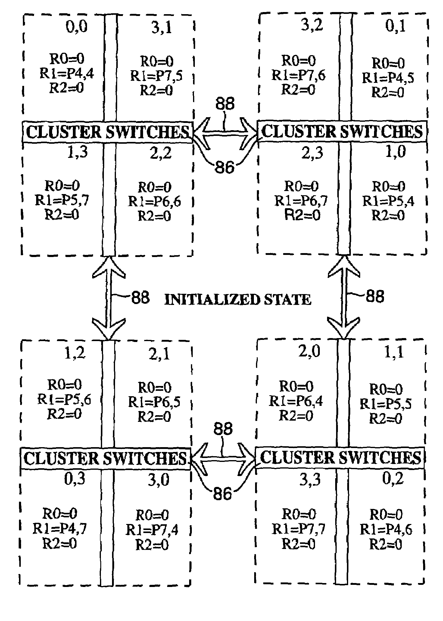
The present invention is about a new type of processing element array that reduces the amount of wiring needed compared to conventional torus processing element arrays. This new array also reduces latency in transpose operations and allows for more efficient communication between processing elements. The array is designed with processing elements grouped into clusters, which helps to minimize inter-cluster communication paths and reduces the length of the longest interconnection wires. The array can be implemented in a cost-effective way and is suitable for integrated circuit manufacturing. Overall, the invention provides a more efficient and compact processing element array for various applications.

Problems solved by technology

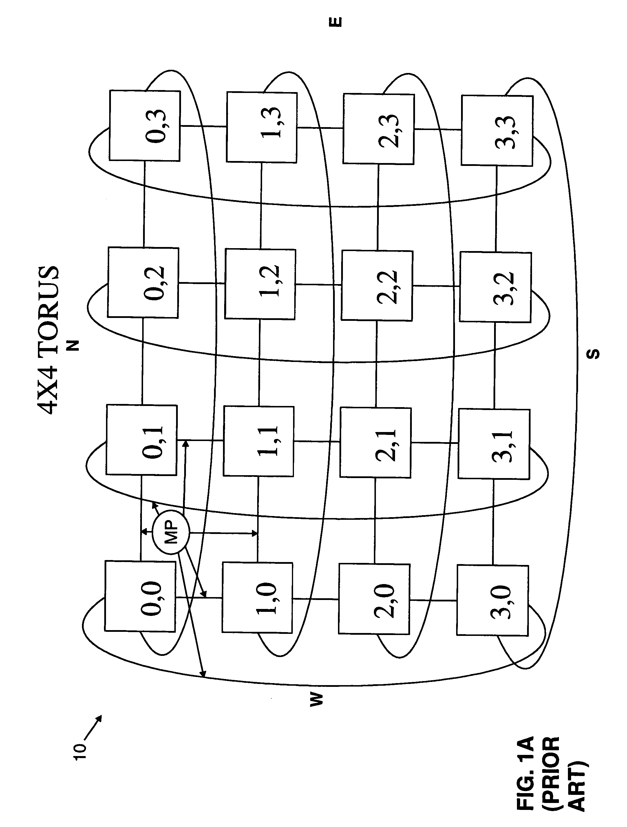
Although bit-serial inter-PE communications are typically employed to minimize wiring complexity, the wiring complexity of a torus-connected array nevertheless presents implementation problems.
Since the total number of wires in a torus connected computer can be significant, the interconnections may consume a great deal of valuable integrated circuit “real estate”, or the area of the chip taken up.
Additionally, the PE interconnection paths quite frequently cross over one another complicating the IC layout process and possibly introducing noise to the communications lines through crosstalk.
Furthermore, the length of wraparound links, which connect PEs at the North and South and at the East and West extremes of the array, increase with increasing array size.
This increased length increases each communication line's capacitance, thereby reducing the line's maximum bit rate and introducing additional noise to the line.
Another disadvantage of the torus array arises in the context of transpose operations.
Naturally, this introduces a delay into the operation, even if PE1,1 and PE2,2 are not otherwise occupied.
Such delays snowball with every intervening PE and significant latency is introduced for the most distant of the transpose pairs.
Due to an overall triangular shape of the arrays, the diagonal fold type of array presents substantial obstacles to efficient, inexpensive integrated circuit implementation.
This fixes the PE's position in the topology, consequently limiting the topology of the PEs and their connectivity to the fixed configuration that is implemented.

Method used


Image

  • Manifold array processor
  • Manifold array processor
  • Manifold array processor

Examples


Embodiment Construction

[0040]In one embodiment, a new array processor in accordance with the present invention combines PEs in clusters, or groups, such that the elements of one cluster communicate with members of only two other clusters and each cluster's constituent processing elements communicate in only two mutually exclusive directions with the processing elements of each of the other clusters. By clustering PEs in this manner, communications paths between PE clusters may be shared, thus substantially reducing the interconnection wiring required for the array. Additionally, each PE may have a single transmit port and a single receive port or, in the case of a bidirectional sequential or time sliced transmit / receive communication implementation, a single transmit / receive port. As a result, the individual PEs are decoupled from the topology of the array. That is, unlike a conventional torus connected array where each PE has four bidirectional communication ports, one for communication in each direction...


PUM


Abstract

An array processor includes processing elements (00, 01, 02, 03, 10, 11, 12, 13, 20, 21, 22, 23, 30, 31, 32, 33) arranged in clusters (e.g., 44, 46, 48, 50) to form a rectangular array (40). Inter-cluster communication paths (88) are mutually exclusive. Due to the mutual exclusivity of the data paths, communications between the processing elements of each cluster may be combined in a single inter-cluster path, thus eliminating half the wiring required for the path. The length of the longest communication path is not directly determined by the overall dimension of the array, as in conventional torus arrays. Rather, the longest communications path is limited by the inter-cluster spacing. Transpose elements of an N×N torus may be combined in clusters and communicate with one another through intra-cluster communications paths. Transpose operation latency is eliminated in this approach. Each PE may have a single transmit port (35) and a single receive port (37). Thus, the individual PEs are decoupled from the array topology.

Description

[0001]This application is a divisional of U.S. Ser. No. 10 / 036,789 filed Dec. 21, 2001 now U.S. Pat. No. 6,892,291 which is a continuation of U.S. Ser. No. 09 / 323,609 filed Jun. 1, 1999, now U.S. Pat. No. 6,338,129 which is a divisional of U.S. Ser. No. 08 / 885,310 filed Jun. 30, 1997, now U.S. Pat. No. 6,023,753 which are incorporated by reference herein in their entirety.BACKGROUND OF THE INVENTION[0002]1. Field of the Invention[0003]The present invention relates to processing systems in general and, more specifically, to parallel processing architectures.[0004]2. Description of the Related Art[0005]Many computing tasks can be developed that operate in parallel on data. The efficiency of the parallel processor depends upon the parallel processor's architecture, the coded algorithms, and the placement of data in the parallel elements. For example, image processing, pattern recognition, and computer graphics are all applications which operate on data that is naturally arranged in two...

Claims


Application Information

Patent Timeline
Patent Type & Authority Patents(United States)
IPC IPC(8): G06F15/16G06F15/80G06F15/173
CPCG06F15/8023G06F15/17337G06F15/00G06F15/17381G06F9/30076
Inventor PECHANEK, GERALD GEORGEKURAK, JR., CHARLES W.
Owner ALTERA CORP
Learn More