Method of photochemically removing ammonia from gas streams

a technology of ammonia gas and photochemical removal, which is applied in the direction of dispersed particle separation, chemistry apparatus and processes, and separation processes, etc., can solve the problem that the ammonia and urea reagent proportion fails to react, reduces the nox control efficiency of the scr system, and the ammonia control techniques available are not well suited for the control of ammonia gas emissions from no/sub>x/sub>control systems. , to achieve the effect o

Inactive Publication Date: 2007-04-03
AIR CONTROL TECHN P C
View PDF2 Cites 26 Cited by
  • Summary
  • Abstract
  • Description
  • Claims
  • Application Information

AI Technical Summary

Benefits of technology

[0027]In one embodiment, the present invention involves irradiation of an ammonia-containing gas stream within the last stage of an SCR catalyst bed and/or on the process gas side of boiler air preheaters. The reactions initiated in the hot, particulate matter-laden gas stream result in the destruction of ammonia gas before it can react with sulfuric acid and other sulfur-containing gases to form sticky deposits of ammonium bisulfate and/or ammonium sulfate. The irradiation employed is ultraviolet light. The treatment of ammonia with radiation in accordanc

Problems solved by technology

Due to the limitations of reagent mixing in the gas stream and the limited residence time of the gas stream in the critical temperature range, a portion of the ammonia and urea reagents fails to react.
This reduces the NOx control efficiency of the SCR system.
Available ammonia control techniques are not well suited for the control of ammonia gas emissions from NOx control systems.
These conventional ammonia wet scrubbers have poor efficiencies for gas streams having low ammonia gas concentrations.
Furthermore, the wet scrubbers require large vessels and liq

Method used


Image

  • Method of photochemically removing ammonia from gas streams
  • Method of photochemically removing ammonia from gas streams
  • Method of photochemically removing ammonia from gas streams

Examples


Embodiment Construction

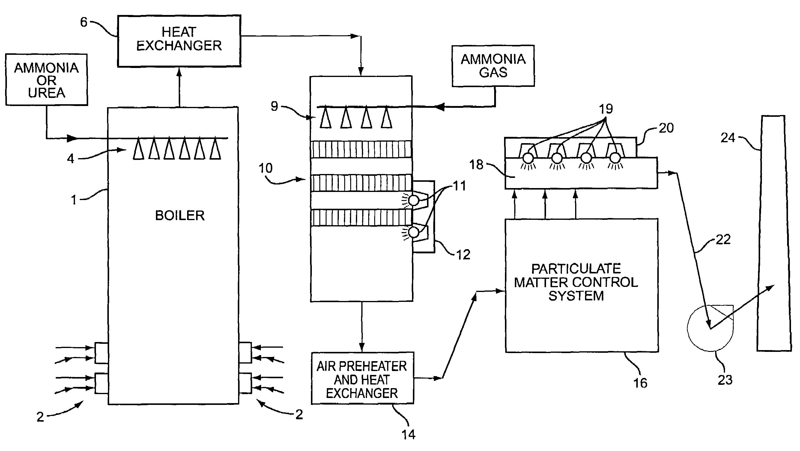
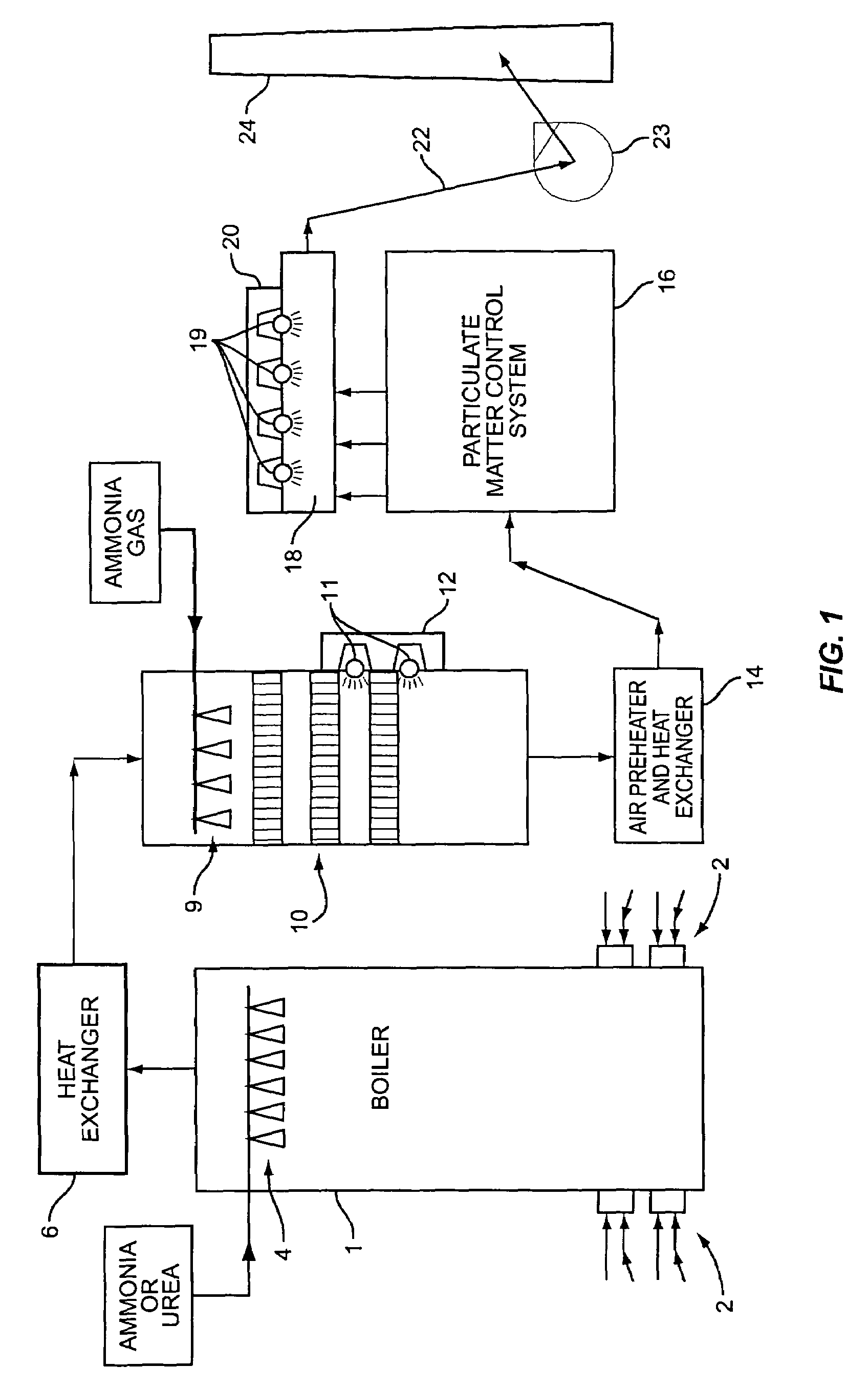
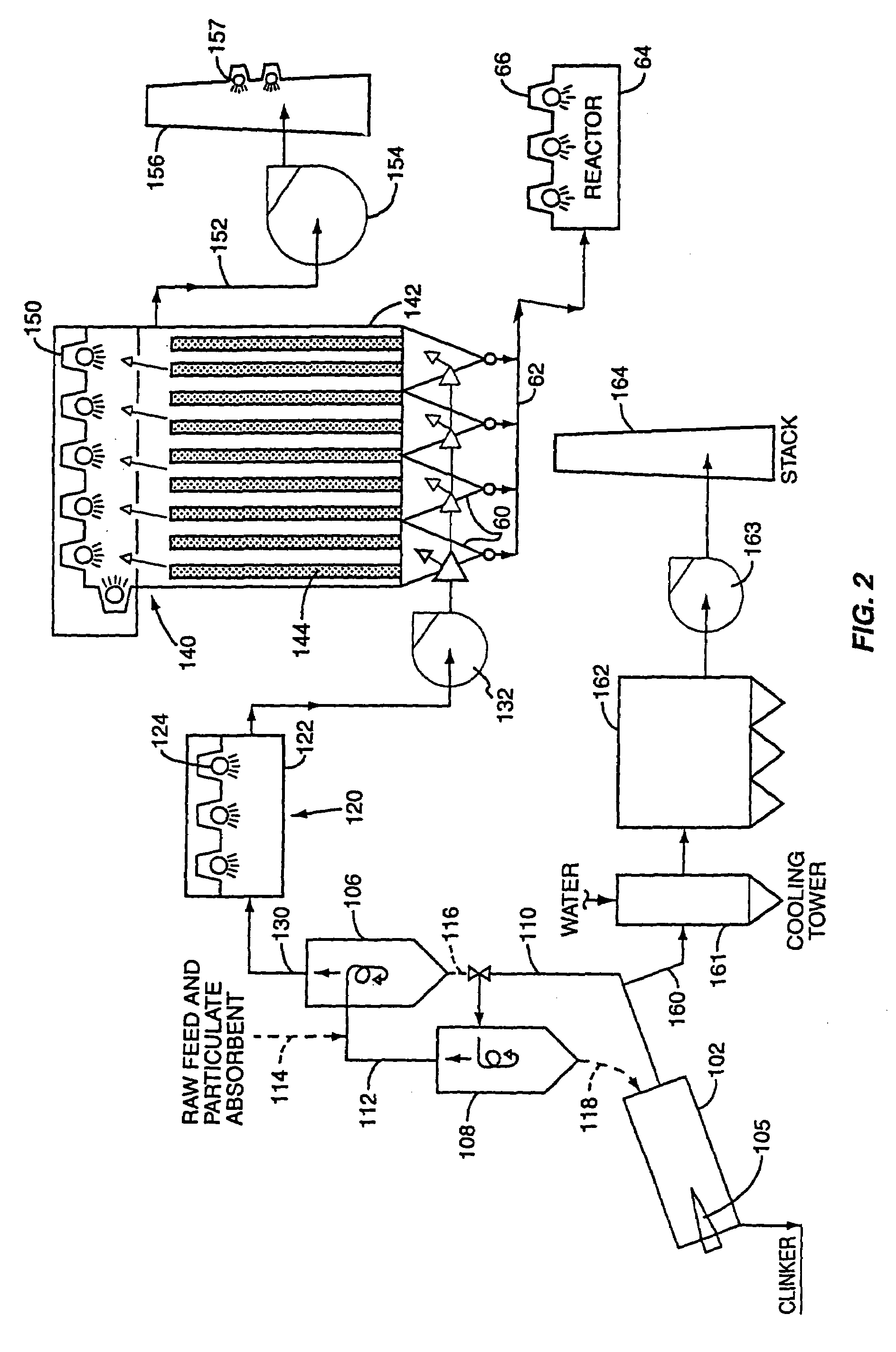
[0036]The ammonia destruction process is applicable to a number of industrial processes, such as coal, oil, and natural gas-fired boilers, wood-fired boilers, waste-fired incinerators, and portland cement plants. In the case of cement plants, the present invention entails irradiating the effluent gas stream that passes from a pyroprocessing system of the cement plant. In this regard, the gas streams are treated in Stage I and Stage II controls with nonphotocatalyzed direct photolysis using irradiated UV light in the spectral range of 230 to 370 nanometers. Stage I control occurs in a particulate matter-laden gas stream located close to the location of ammonia gas generation in the industrial process stream and is intended to protect downstream equipment from corrosive and sticky ammonium compounds. Stage II control is performed in a gas stream that has been treated in a high efficiency particulate matter control system to reduce the particulate matter concentrations by a factor of 9...


PUM

PropertyMeasurementUnit
Fractionaaaaaaaaaa
Fractionaaaaaaaaaa
Nanoscale particle sizeaaaaaaaaaa

Abstract

The present invention entails a method of removing ammonia from a gas stream. The method entails irradiating the gas stream with light in the spectral range of 200–350 nanometers and disassociating hydrogen free radicals from ammonia to form NH2. Once NH2 is formed, then reacting the NH2 with NOx to form N2 and water. In one specific embodiment of the present invention, the method entails removing ammonia from a gas stream associated with a cement producing process. In particular, a raw feed is directed into a pyroprocessing system of a cement manufacturing facility. This raw feed is heated and in the process of producing cement, a gas stream results. Ammonia present in the gas stream is removed or substantially reduced by irradiating the gas stream and disassociating hydrogen free radicals from the ammonia to form NH2. NH2 is then reacted with NOx to form water.

Description

CROSS REFERENCE TO RELATED APPLICATIONS[0001]This is a continuation-in-part of U.S. patent application Ser. No. 10 / 269,204 filed Oct. 11, 2002, now abandoned which was a continuation-in-part of U.S. patent application Ser. No. 09 / 847,476 filed May 2, 2001, now U.S. Pat. No. 6,541,677, and U.S. patent application Ser. No. 10 / 098,759 filed Mar. 14, 2002, now U.S. Pat. No. 6,770,174.FIELD OF THE INVENTION[0002]Photochemically initiated free radical reactions involving nitrogen oxides (NOx), carbon monoxide (CO), hydrocarbons, and water vapor are used to oxidize ammonia gas in the effluent gas streams leaving nitrogen oxides control systems. It is known that selective catalytic reduction (SCR) systems and selective noncatalytic reduction (SNCR) systems generate limited quantities of ammonia gas. The ability to control nitrogen oxides by SCR and SNCR systems is often limited by the need to avoid high concentrations of ammonia and by the formation of ammonium compounds that can accumulate...

Claims


Application Information

Patent Timeline
IPC IPC(8): B01D53/00
CPCB01D53/007B01D53/58B01D53/8625B01D2251/2062B01D2259/804Y02A50/20
Inventor RICHARDS, JOHN R.GOSHAW, DAVID G.
Owner AIR CONTROL TECHN P C
Why Eureka
Try Eureka