
Magnetic memory cell junction and method for forming a magnetic memory cell junction

a magnetic memory cell and junction technology, applied in the field of magnetic memory cell junction and the method of etching a semiconductor topography, can solve the problems of reducing the reliability of the memory array, false bit being unintentionally written to one or more cells, and the proportion of the stack of layers to be undercut, so as to achieve high reliability, reduce the likelihood of shortening the tunneling barrier layer of the patterned magnetic cell junction, and tighten the switching field distribution

Active Publication Date: 2007-04-03
MONTEREY RES LLC
View PDF17 Cites 4 Cited by
  • Summary
  • Abstract
  • Description
  • Claims
  • Application Information

AI Technical Summary

Benefits of technology

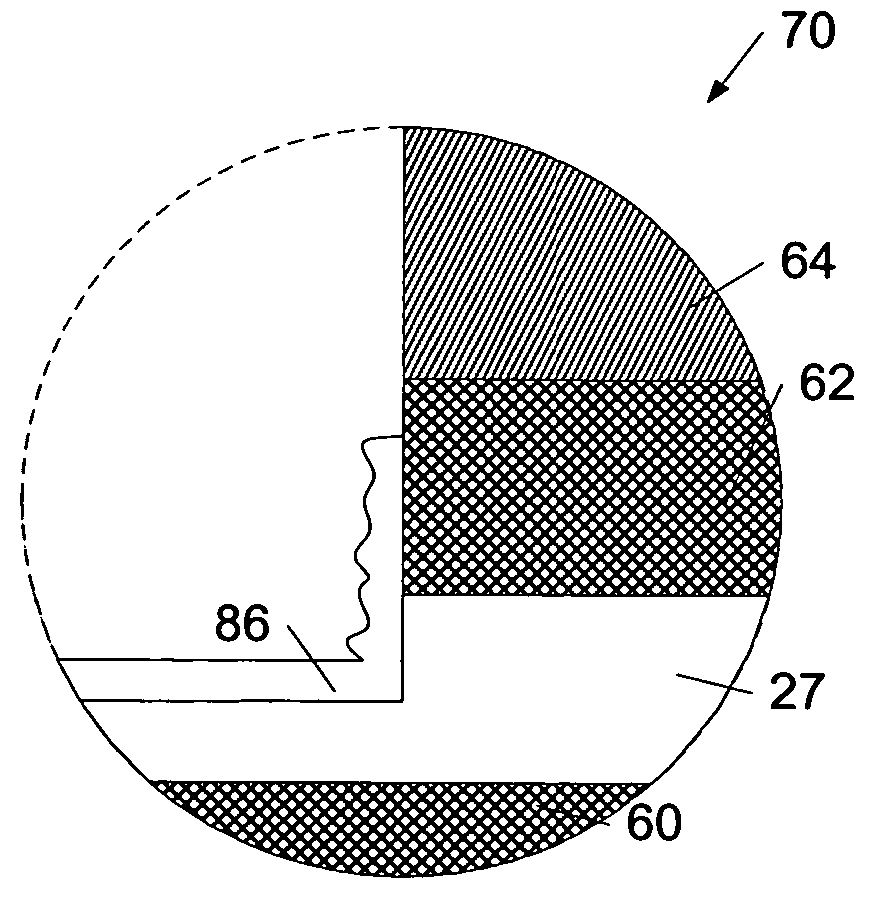
[0015]In some embodiments, such a method may generate veils along sidewalls of the patterned stack of layers during the etching steps. In general, “veils” may refer to the material redeposited upon the sidewall surfaces of the patterned magnetic cell junction during the etch process. In some cases, the method may include etching the stack of layers with a high density plasma such that the number of veils produced may be less than the number of veils produced when dry etch techniques, such as ion milling and / or reactive ion etching, are used for the etch processes. In any case, the method may include subsequent steps of implanting dopants into the generated veils. Since the method includes alternating the steps of etching and implanting in such an embodiment, the etch processes conducted subsequent to each of the implanting steps may remove the previously doped veils. Consequently, the number of veils along the sidewalls of a magnetic cell junction subsequent to the patterning process may be reduced or eliminated relative to a magnetic cell junction patterned using conventional techniques. As a result, the likelihood for forming shorts across the tunneling barrier layer of the patterned magnetic cell junction may be reduced or eliminated using the method described herein. In a preferred embodiment, alternating the steps of etching and implanting may include etching a greater amount of the stack of layers than the amount of the stack of layers implanted with dopants during the step of implanting.
[0016]There may be several advantages for patterning a magnetic cell junction using the methods described herein. For example, a magnetic cell junction may be patterned which is less susceptible to the formation of veils along its sidewall surfaces. As a result, the formation of shorts across the tunneling barrier layer of the magnetic cell junction may be less prone to occur with the methods described herein. In addition, the methods described herein offer a manner in which to pattern a magnetic cell junction without altering the magnetic balance of the reference portion of the cell junction. Furthermore, the methods described herein offer a manner in which to form a magnetic cell junction having lateral dimensions within the design specifications of the magnetic cell junction. In this manner, a memory array with high reliability may be fabricated. In particular, a memory array adapted to write bits to correct locations while inhibiting the writing of false bits may be fabricated. Consequently, a memory array fabricated using the methods described herein may operate with a tighter switching field distribution.

Problems solved by technology

Such a technique, however, may cause some portions of the stack of layers to be undercut.
In general, variations of cell junction sizes and shapes may cause the amount of current needed to switch the magnetic direction of memory cells to vary, reducing the reliability of the memory array.
In particular, size and shape variations of the cell junctions within an array may allow a false bit to be unintentionally written to one or more cells.
Such dry etch techniques, however, often cause material removed from the stack of layers to be redeposited upon sidewalls of the patterned magnetic cell junctions.
In some cases, such a redeposition of material may alter the functionality of the memory array or render the memory array inoperable.
In particular, the redeposition of material along the sidewalls of a magnetic cell junction may produce shorts across the tunneling barrier layer of the cell junction, prohibiting the logic state of the magnetic cell junction from being determined.
Controlling the depth of oxidation using a robust oxidation process, however, is often difficult.
Consequently, lower layers of the stack of layers may be undesirably oxidized.
In some cases, such a change in the magnetic balance of the reference portion may cause the magnetic cell junction to malfunction, reducing the reliability of the memory array.

Method used


Image

  • Magnetic memory cell junction and method for forming a magnetic memory cell junction
  • Magnetic memory cell junction and method for forming a magnetic memory cell junction
  • Magnetic memory cell junction and method for forming a magnetic memory cell junction

Examples


Embodiment Construction

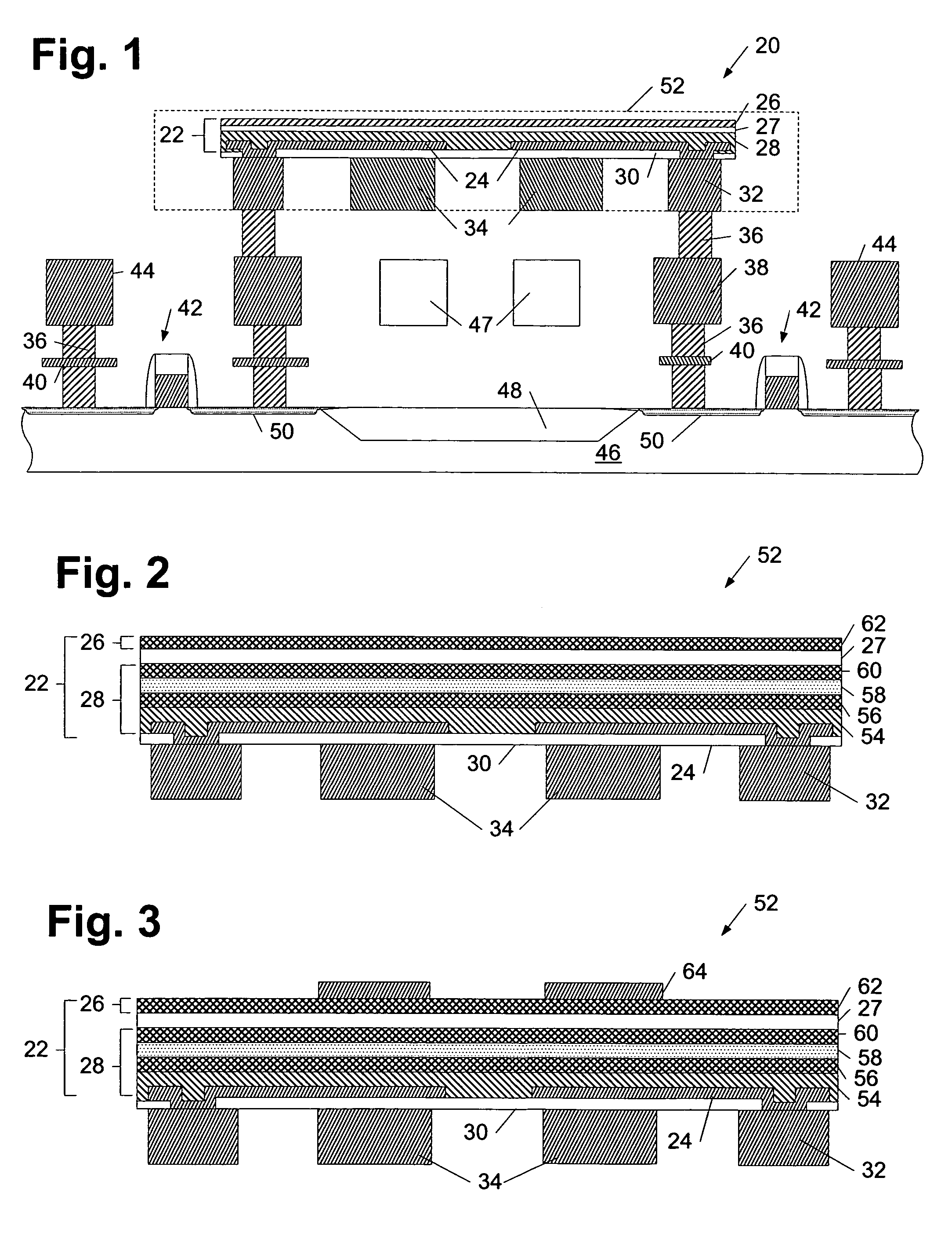
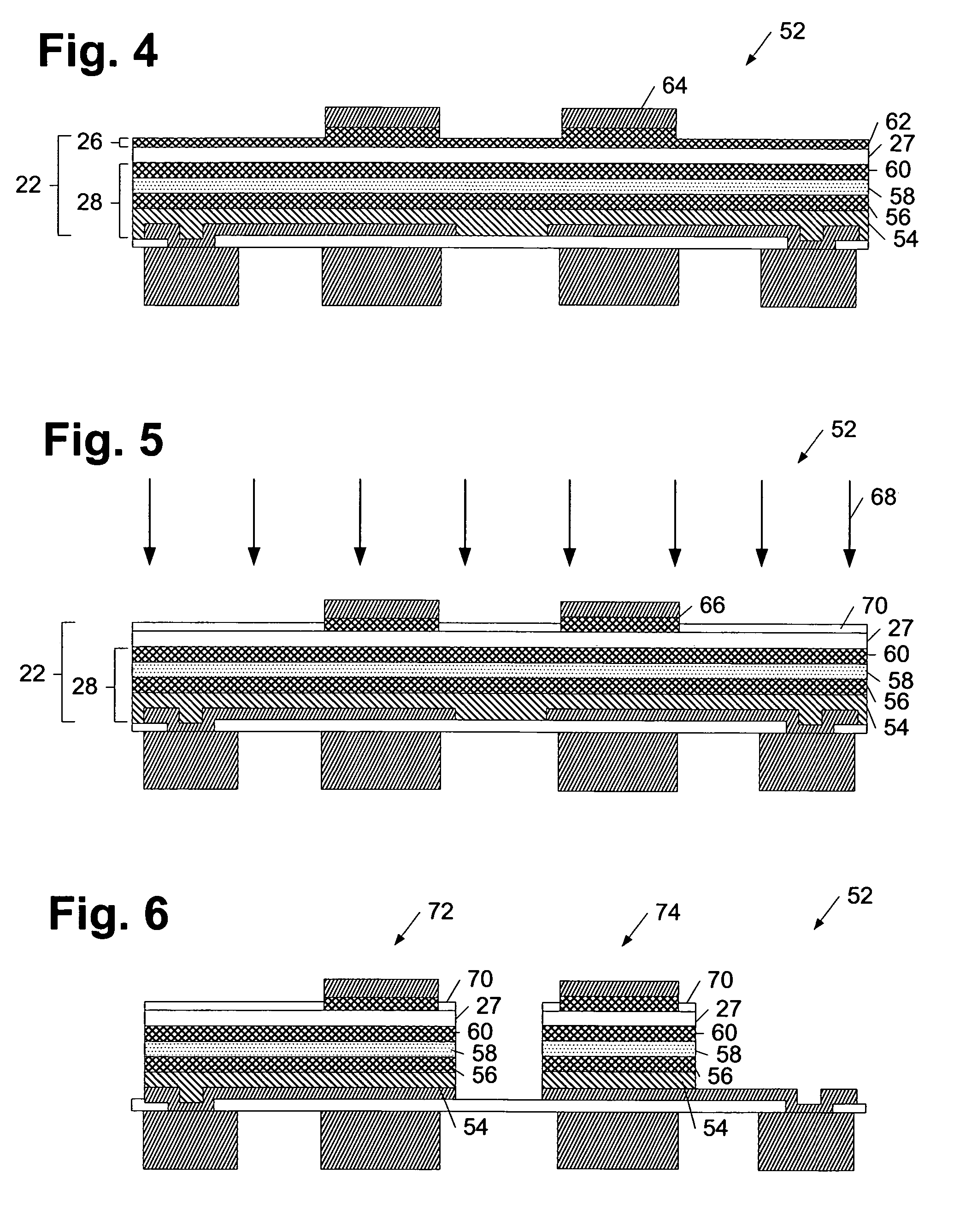
[0034]Turning to the drawings, exemplary embodiments of methods for patterning a magnetic cell junction are provided. In particular, FIGS. 4–6 illustrate a method in which exposed portions of a stack of layers are etched to a level above a tunneling barrier layer and remaining portions of the layers above the tunneling barrier layer are implanted with dopants such that a lower portion of the magnetic cell junction may be patterned. On the other hand, FIGS. 7a–11 illustrate a method which includes successively repeating the steps of etching and implanting dopants throughout the entirety of the stack of layers such that the entirety of the magnetic cell junction is patterned in a continuous process. An exemplary microelectronic topography which may be used for such methods is described in FIGS. 1–3. In particular, FIG. 1 depicts a partial cross-sectional view of microelectronic topography 20 which includes plurality of layers 22 formed above electrodes 24. As will be described in more...


PUM


Abstract

A method for patterning a magnetic memory cell junction is provided herein, which includes etching exposed portions of a stack of layers to a level spaced above a tunneling barrier layer of the stack of layers. In addition, the method may include implanting dopants into exposed portions of the stack of layers. For example, the method may include oxidizing and / or nitriding the exposed portions of the stack of layers. In some embodiments, the steps of etching and implanting dopants may form an upper portion of the magnetic cell junction. Alternatively, the method may include alternating the steps of etching and implanting dopants throughout the thickness of the exposed portions of the stack of layers. In either case, the stack of layers may include a magnetic layer which includes a material adapted to prevent the introduction of dopants underlying the tunneling barrier layer during the step of implanting.

Description

PRIORITY APPLICATION[0001]This application claims priority to provisional application No. 60 / 451,483 entitled “Magnetic Memory Cell Junction and Method for Forming a Magnetic Memory Cell Junction,” filed Mar. 3, 2003.BACKGROUND OF THE INVENTION[0002]1. Field of the Invention[0003]This invention relates to semiconductor device manufacturing, and more particularly, to a method for etching a semiconductor topography.[0004]2. Description of the Related Art[0005]The following descriptions and examples are not admitted to be prior art by virtue of their inclusion within this section.[0006]Recently, advancements in the use of magnetoresistive materials have progressed the development of magnetic random access memory (MRAM) devices to function as viable non-volatile memory circuits. In general, MRAM circuits exploit the electromagnetic properties of magnetoresistive materials to set and maintain information stored within individual magnetic memory cell junctions of the circuit. In particula...

Claims


Application Information

Patent Timeline
IPC IPC(8): H01L21/302H01L21/461G11CH01L21/00H01L21/8239H01L21/8246H01L27/22H01L29/82H01L43/08H01L43/12
CPCB82Y10/00H01L43/12H01L27/228H10B61/22H10N50/01
Inventor CHEN, EUGENE Y.OUNADJELA, KAMELKULA, WITOLDWOLFMAN, JEROME S.
Owner MONTEREY RES LLC
Learn More