
System and method for a passively Q-switched, resonantly pumped, erbium-doped crystalline laser

a crystalline laser and resonant pump technology, applied in the field of lasers, can solve the problems of high cost, complex and costly implementation, and the limit gain needed to efficiently produce high peak power pulses at prfs much greater than 1 kilohertz, and achieve photon quantum efficiency near 63%

Active Publication Date: 2007-04-10
BAE SYST INFORMATION & ELECTRONICS SYST INTEGRATION INC
View PDF14 Cites 39 Cited by
  • Summary
  • Abstract
  • Description
  • Claims
  • Application Information

AI Technical Summary

Problems solved by technology

The former has been successfully demonstrated with Nd-pumped Raman converters or optical parametric oscillators (OPOs) (with or without optical parametric amplifiers (OPAs)) but implementation has proven to be complex and costly.
The latter has been the traditional approach for high peak power, eyesafe pulse generation at low to moderate (approximately 3 to 1000 Hertz (Hz)) pulse repetition frequencies (PRFs), but several problems in Yb-sensitized Er glass lasers limit gain needed to efficiently produce high peak power pulses at PRFs much greater than 1 kilohertz (kHz).
3) With pump lasers at approximately 980 nm, the radiationless transition involved in the population of Erbium's upper lasing state (for 1.5 micron lasing) generates additional waste heat and renders the photon quantum efficiency near 63%; the latter limiting efficiency and the former tending to destabilize the laser resonator.
Due to the cavity dimensions associated with them, these resonantly pumped actively Q-switched Erbium lasers will struggle to produce pulse widths substantially less than 20 ns and still have peak powers greater than 1 kW.
Hence, for example, they will remain inefficient in applications such as scanning LADAR, wherein resolution requirements prefer less than 3 ns pulse widths for efficient operation.
With its aforementioned inherent limitations of quantum defect, waste heat and energy storage bottleneck issues discussed above, sensitizer doped Er:glass passively Q-switch lasers have difficulty achieving these results.
Thus, a heretofore unaddressed need exists in the industry to address the aforementioned deficiencies and inadequacies.

Method used


Image

  • System and method for a passively Q-switched, resonantly pumped, erbium-doped crystalline laser
  • System and method for a passively Q-switched, resonantly pumped, erbium-doped crystalline laser
  • System and method for a passively Q-switched, resonantly pumped, erbium-doped crystalline laser

Examples


Embodiment Construction

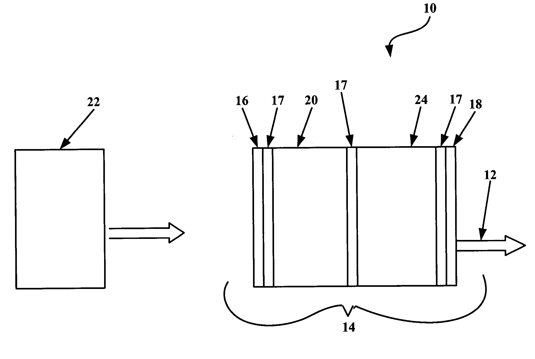
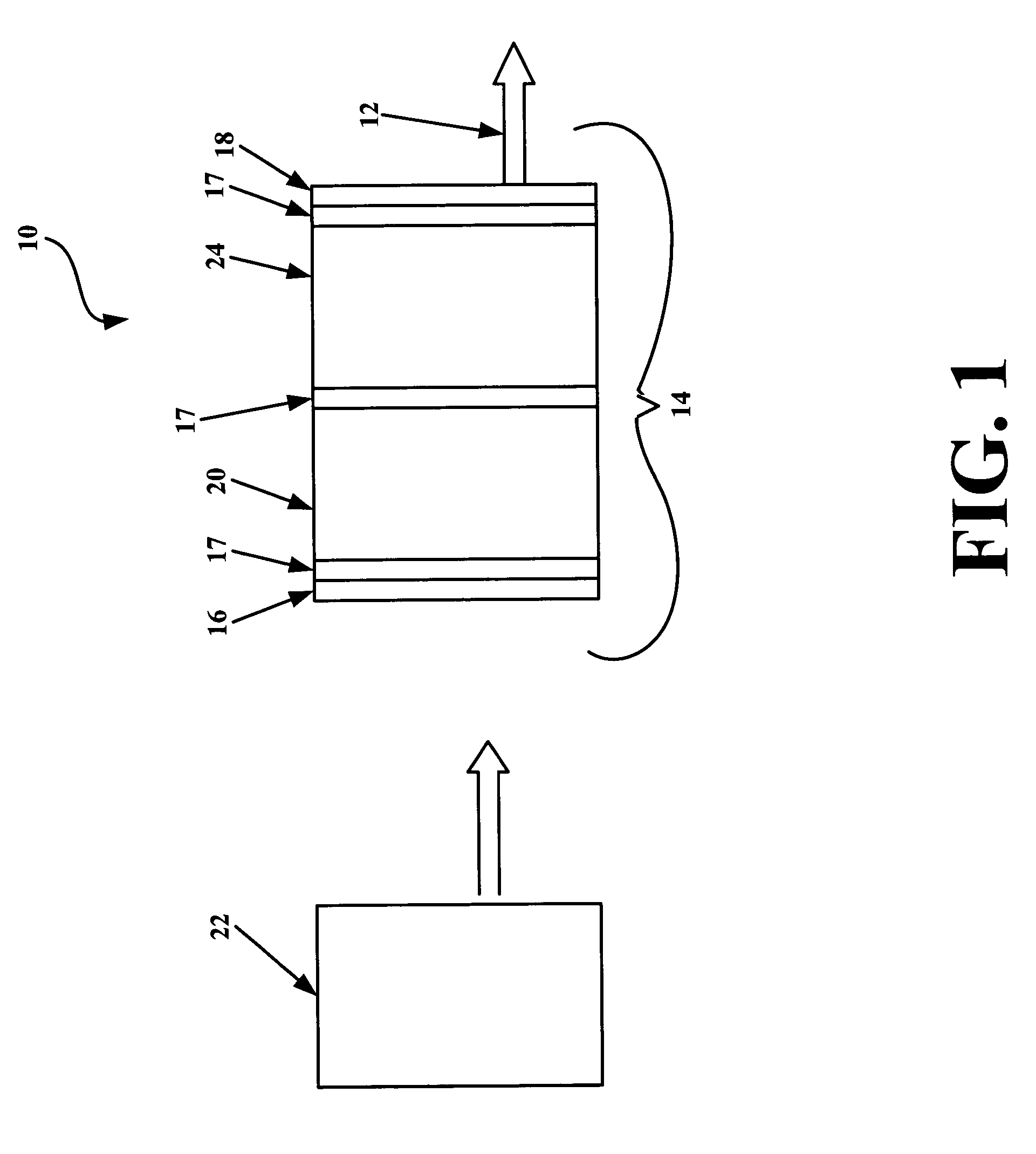
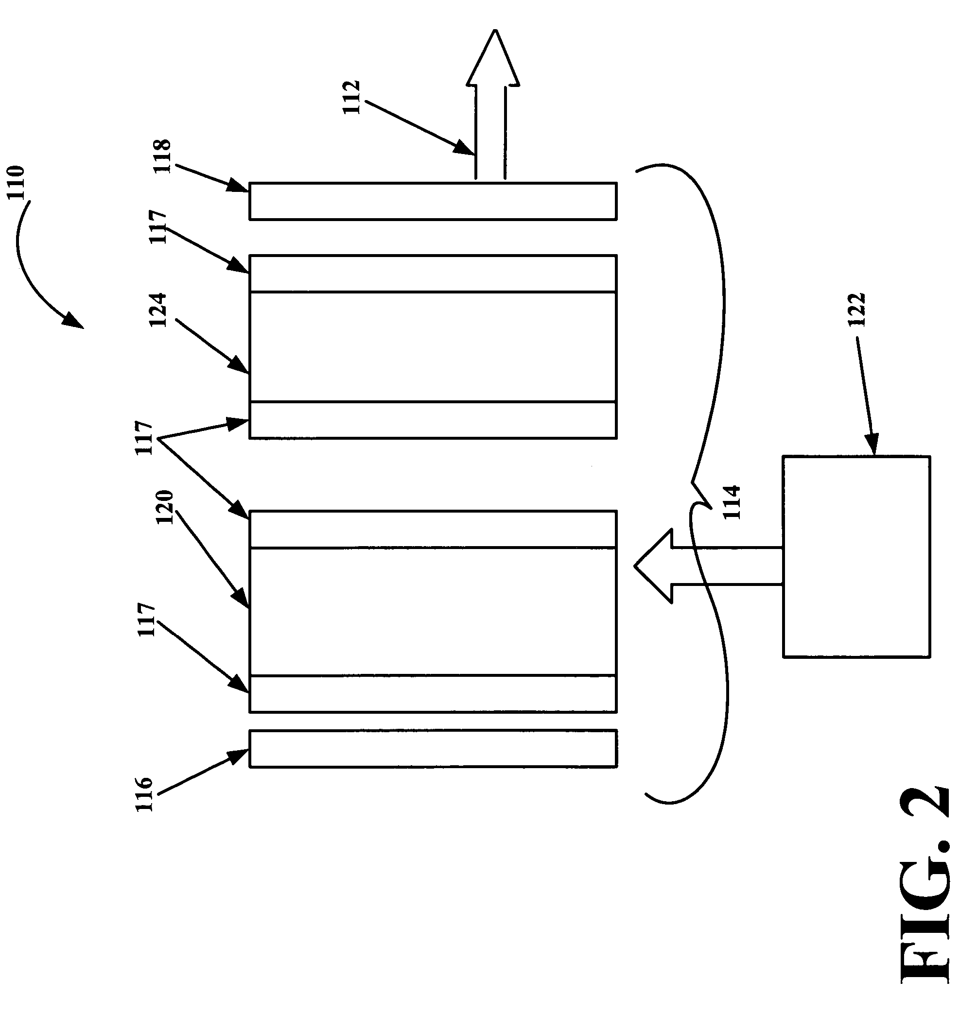
[0017]FIG. 1 is a cross-sectional view of a laser 10 for producing output pulses 12, in accordance with a first exemplary embodiment of the invention. The laser 10 includes a resonant cavity 14 formed between a first mirror 16 and a second mirror 18. An unsensitized Erbium-doped crystal gain medium 20 is disposed within the resonant cavity 14 for producing laser gain. A saturable absorber 24 is disposed within the resonant cavity 14. A face cooling end cap 17 may be placed in contact with, or be an integral part of (e.g. undoped region), either the gain medium 20, or the saturable absorber 24, or both. A pump source 22 is positioned to energize the gain medium 20. The saturable absorber 24, the laser gain 20, the resonator length, and the second mirror 18 are selected so that output pulses 12 each have a duration of less than 75 ns, thereby generating short, high-peak power pulses.

[0018]The pump source 22 may be a diode laser, a fiber laser, solid state laser, or another pump source...


PUM


Abstract

The laser includes a resonant cavity formed between a first mirror and a second mirror. An unsensitized Erbium-doped crystal gain medium for producing laser gain is disposed within the resonant cavity. A saturable absorber is disposed within the resonant cavity. A pump source is positioned to energize the gain medium. The saturable absorber, the laser gain, the resonator length, and the second mirror being selected so that output pulses having a duration of less than 75 nanoseconds are generated by the laser.

Description

FIELD OF THE INVENTION[0001]The present invention relates to the field of lasers and, more specifically, passively Q-switched, eye safe lasers.BACKGROUND OF THE INVENTION[0002]The need for short pulse (approximately <75 nanoseconds (ns)), high peak power (approximately 10 Kilowatt (kW)), eyesafe (approximately 1.4–1.7 micrometers (microns)) lasers has arisen in both military and commercial arenas. Scanning light detecting and ranging (LADAR) and target identification are examples of military applications needing such lasers, with free space communications likely the largest relevant commercial application.[0003]Traditionally, sources for high peak power, eyesafe wavelength lasers have been wavelength-shifted Neodymium (Nd)-pumped wavelength shifters or Ytterbium (Yb)-sensitized Erbium (Er) lasers. The former has been successfully demonstrated with Nd-pumped Raman converters or optical parametric oscillators (OPOs) (with or without optical parametric amplifiers (OPAs)) but impleme...

Claims


Application Information

Patent Timeline
Patent Type & Authority Patents(United States)
IPC IPC(8): H01S3/11H01S3/113
CPCH01S3/0627H01S3/09415H01S3/0405H01S3/0604H01S3/0612H01S3/094084H01S3/0941H01S3/1118H01S3/113H01S3/1608H01S3/1653H01S3/2308
Inventor YOUNG, YORK E.SETZLER, SCOTT D.
Owner BAE SYST INFORMATION & ELECTRONICS SYST INTEGRATION INC
Learn More