
X-ray tube of the end window type, and an X-ray fluorescence analyzer

a fluorescence analyzer and x-ray tube technology, applied in the direction of x-ray tube electrodes, x-ray tube vessels/containers, x-ray tube target materials, etc., can solve the problems of weakening the analytical performance of the x-ray fluorescence analyzer in measuring soil pollution, giving enough bremsstrahlung, and high intensity of bremsstrahlung

Active Publication Date: 2007-04-10
HITACHI HIGH TECH ANALYTICAL SCI FINLAND OY
View PDF4 Cites 41 Cited by
  • Summary
  • Abstract
  • Description
  • Claims
  • Application Information

AI Technical Summary

Benefits of technology

[0006]An objective of the present invention is to provide a controllable X-ray source that is capable of producing an excitation spectrum that has both good characteristic peaks and a high intensity of bremsstrahlung. Another objective of the invention is to provide an X-ray fluorescence analyzer that has good analytical performance in measuring the heavy metal content of target samples. Yet another objective of the invention is to provide a versatile anode solution for use in a wide range of end window type X-ray tube applications.
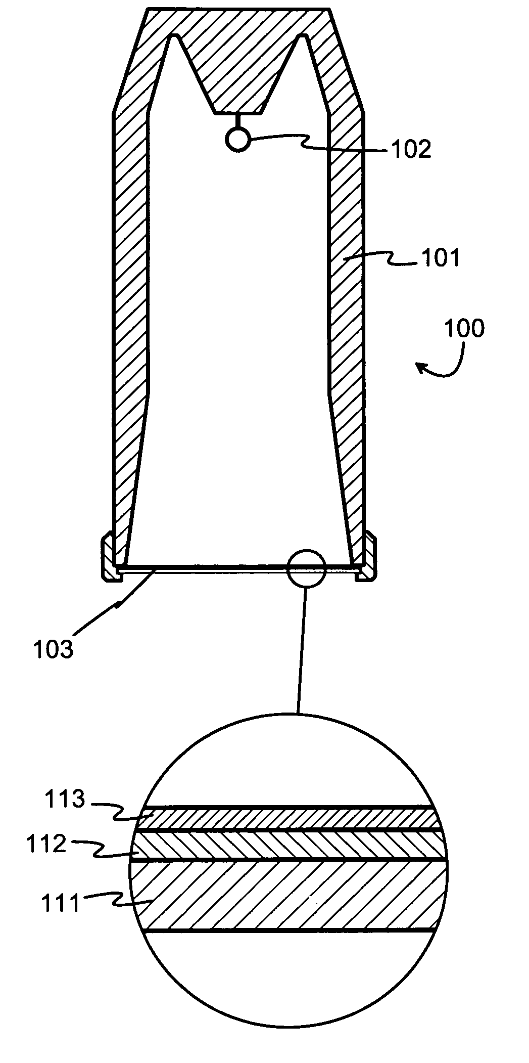
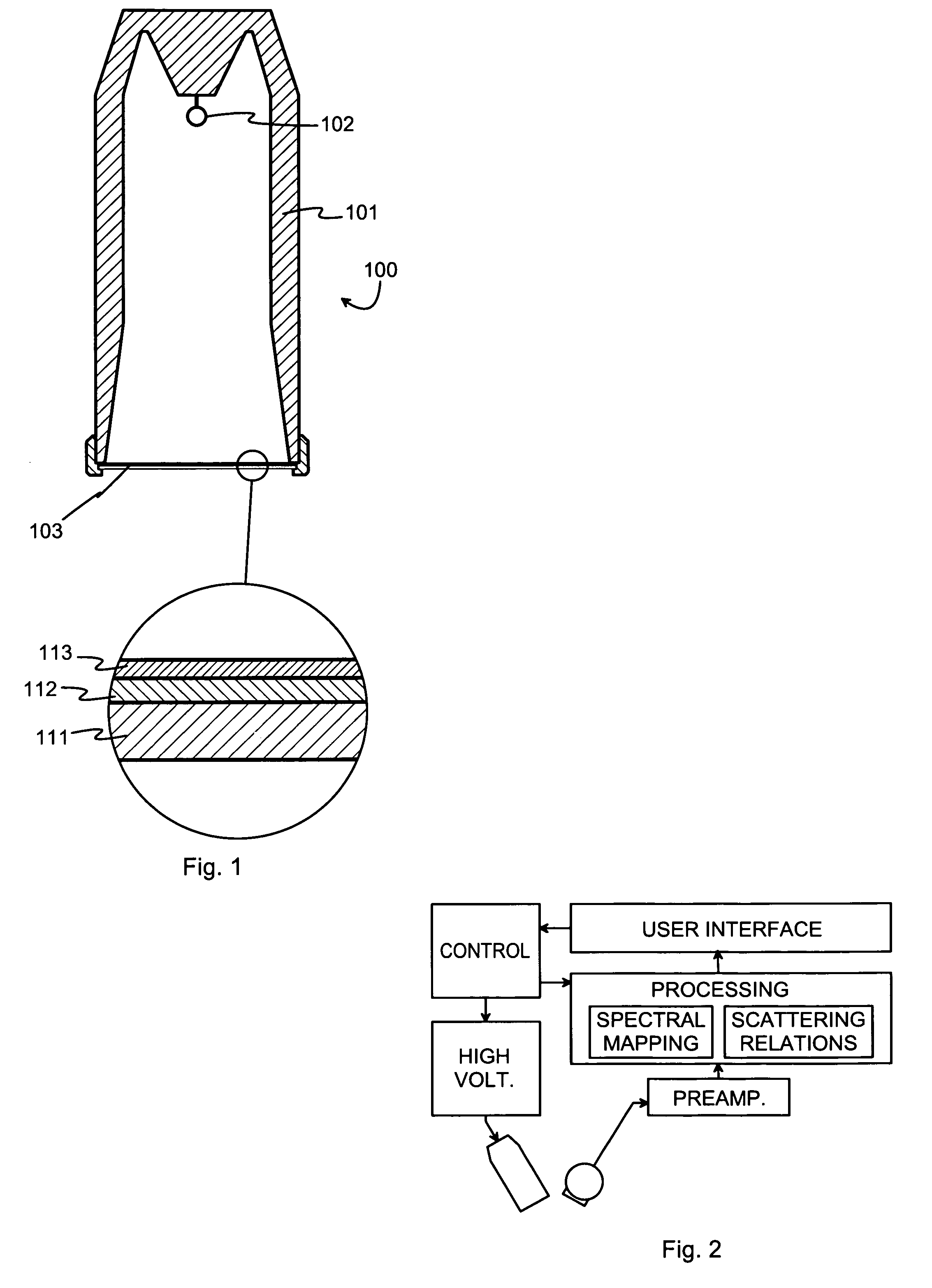
[0008]According to an aspect of the present invention, by using two anode layers and suitable dimensioning it is possible to achieve a situation, in which some of the accelerated electrons interact within a “heavy” anode layer producing a relatively high amount of bremsstrahlung, while others interact with a “light” anode layer producing at least one prominent characteristic peak at a spectral location characteristic to that anode material.

Problems solved by technology

A problem with selecting the anode material occurs, because an anode material that gives good characteristic peaks does not necessarily give enough bremsstrahlung in the desired energy ranges.
However, the amount of bremsstrahlung coming from a rhodium anode is relatively low in the frequency range that would be required to properly excite the atoms of cadmium, which is a typical pollutant to be measured from soil.
Thus using a rhodium anode results in a relatively low intensity of fluorescent radiation from cadmium and other heavy metals, which weakens the analytical performance of the X-ray fluorescence analyzer in measuring soil pollution.

Method used


Image

  • X-ray tube of the end window type, and an X-ray fluorescence analyzer
  • X-ray tube of the end window type, and an X-ray fluorescence analyzer

Examples


Embodiment Construction

[0015]FIG. 1 is a schematic cross section of an X-ray tube 100 of the end window type. An airtight housing 101 is designed to maintain essentially vacuum conditions inside it. Within the housing 101 there is a cathode arrangement 102 designed to emit electrons, for example as the result of heating up a cathode wire coupled to a high negative voltage. At one end of the housing 101 there is an end window, which is generally designated as 103. As is seen in more detail in the partial enlargement, the end window 103 has a layered structure. A carrier layer 111 is made of a material that is mechanically strong, chemically stable and permeable to X-rays. A preferred material for the carrier layer 111 is beryllium, but also other materials can be used that are known for their suitability for radiation-passing windows of X-ray tubes.

[0016]On the inner surface of the carrier layer 111 there is a layered anode arrangement. A strong electric field between the cathode arrangement 102 and the an...


PUM


Abstract

In an x-ray tube comprising a housing, which define an enclosure, a cathode arrangement, which emits electrons within the enclosure, and a window, which seals an end of the enclosure, the window comprises a carrier layer and, on a side of the carrier layer that faces the enclosure, a layered anode arrangement having certain characteristics.

Description

TECHNICAL FIELD[0001]The invention concerns the technical field of controllable x-ray sources that are applicable for use e.g. in measurement systems where X-rays are needed as excitation radiation. Especially the invention concerns adapting the structure of an X-ray tube to comply with requirements of producing radiation of a particular kind.BACKGROUND OF THE INVENTION[0002]An X-ray tube is a controllable X-ray source, in which electrons detached from a cathode get accelerated in an electric field and hit an anode, where they lose their kinetic energy in various interaction processes with the atoms of the anode material. One result of these interaction processes is the generation of X-rays, the spectrum of which comprises both a continuous part (known as bremsstrahlung) and some prominent peaks. The energies at which the peaks occur depend on the anode material, because the peaks are associated with the relaxation of excited states in the atoms of the anode. Widely used anode mater...

Claims


Application Information

Patent Timeline
IPC IPC(8): H01J35/08
CPCH01J35/08H01J35/18H01J2235/081H01J2235/087H01J2235/088H01J2235/183H01J2235/186H01J35/116H01J35/186
Inventor PUUSAARI, ERKKI TAPANI
Owner HITACHI HIGH TECH ANALYTICAL SCI FINLAND OY
Learn More