Optical wireless link

a wireless link and optical technology, applied in the field of optical data communication, can solve the problems of limited effective bandwidth, high cost of links, and inability to install or upgrade systems in practical terms

Inactive Publication Date: 2007-04-10
TEXAS INSTR INC
View PDF30 Cites 21 Cited by
  • Summary
  • Abstract
  • Description
  • Claims
  • Application Information

AI Technical Summary

Benefits of technology

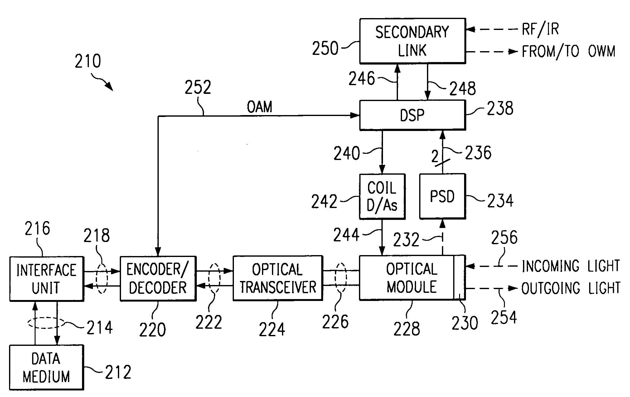
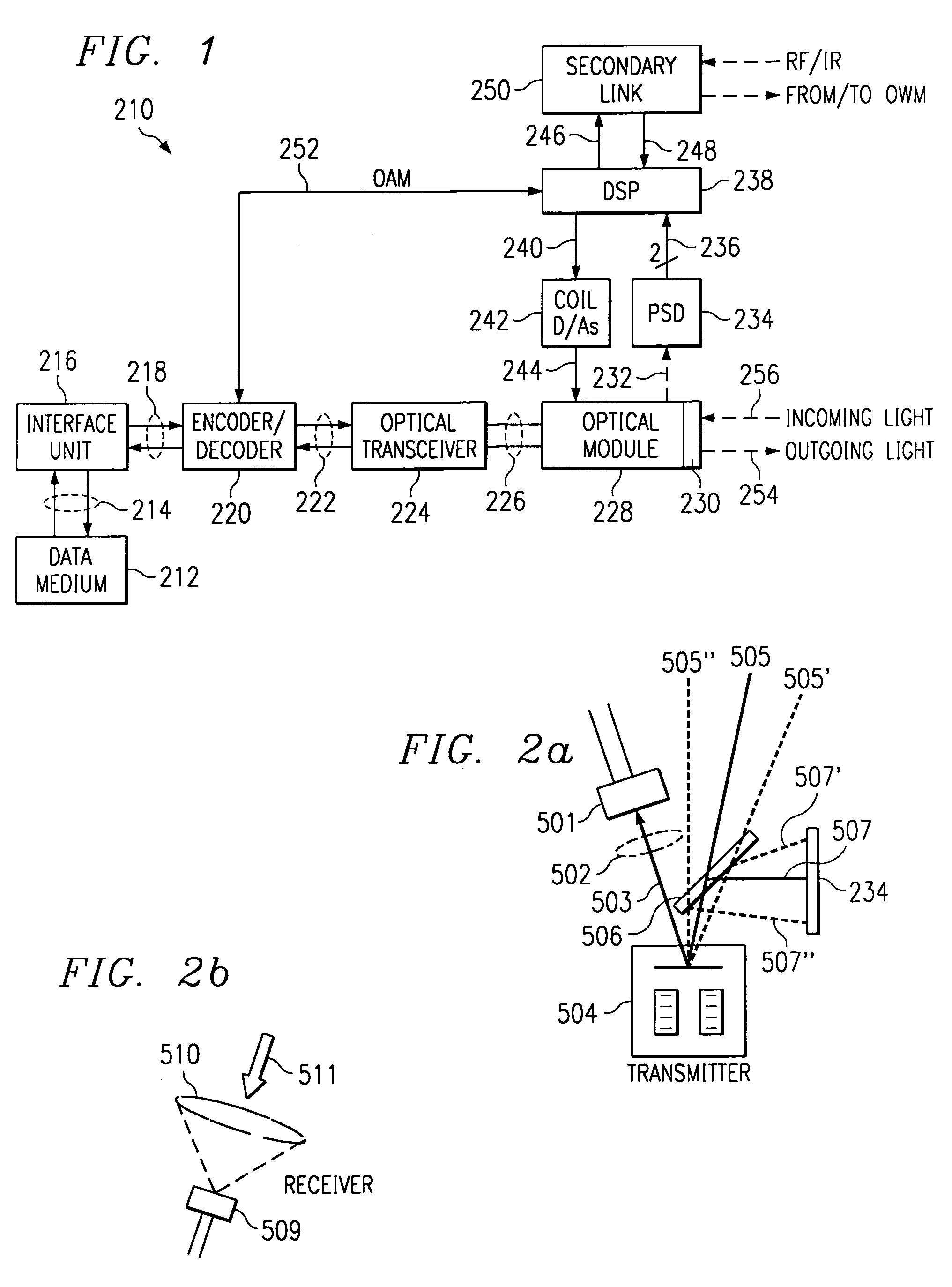
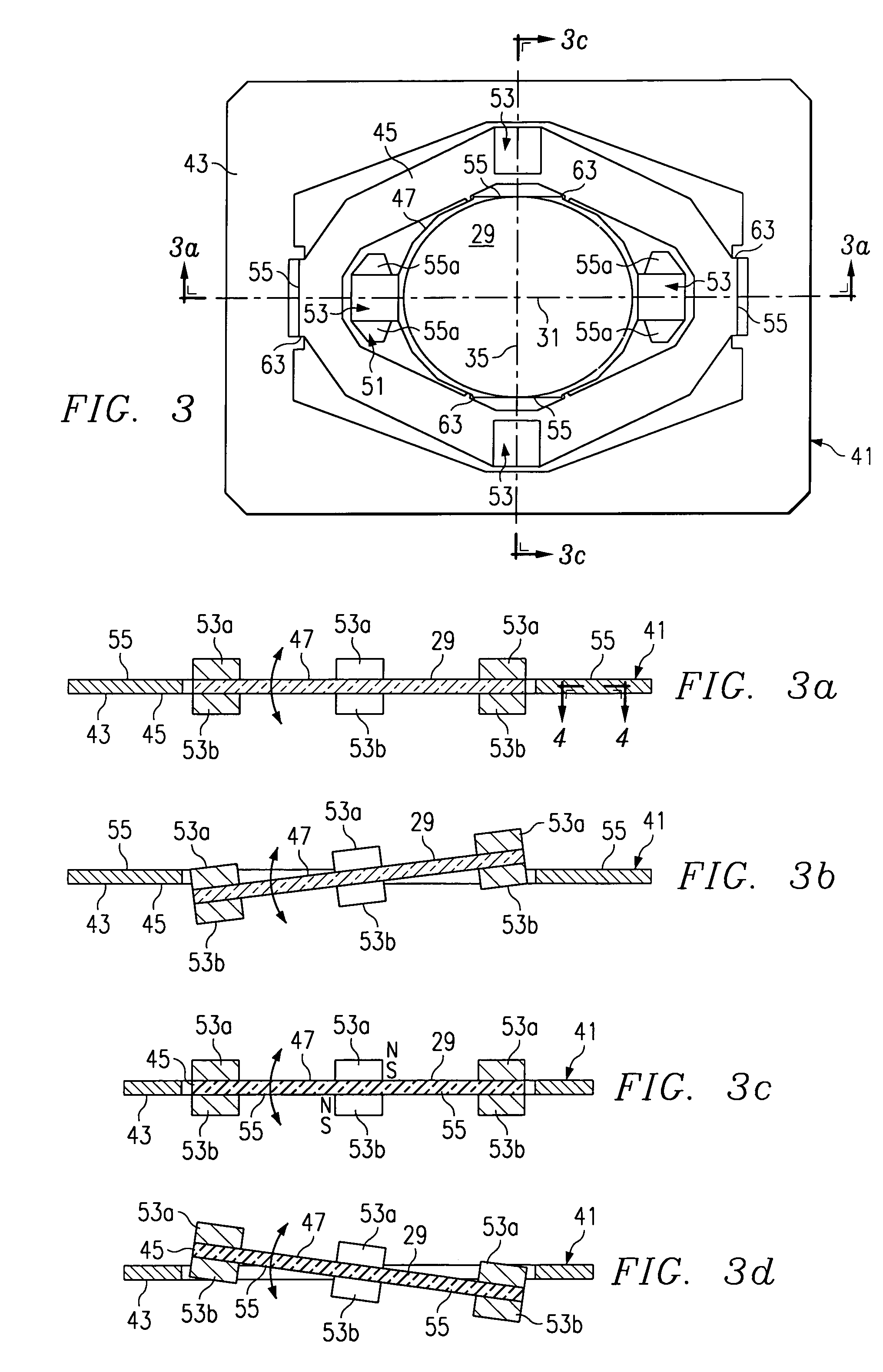
[0004]In accordance with the present invention there is provided an optical, path-to-sight modem. The modem includes a controllable beam steering device, such as, for example, a micro-mirror, or any other device that changes the direction of the light beam without changing the orientation of the light emitter and includes an actuator to permit steering the light beam, the beam steering device being controllab

Problems solved by technology

However, the time and expense of installing physical cabling or fiber between network or device nodes in many cases prohibits the practical installation or upgrading of systems.
However, such links share bandwidth across multiple users in an area, provide access to the RF signal by all users resulting in security concerns, are subject to FCC r

Method used


Image

  • Optical wireless link
  • Optical wireless link
  • Optical wireless link

Examples


embodiment 300

[0092]A further embodiment 300 of the present invention is shown in FIG. 12, and will now be described, for transmitting a composite analog video signal using a collimated light beam reflected off a beam steering micro-mirror. The source of the video signal is a composite video co-ax output of a DVD player 302. The DVD video output is connected to an interface unit 304, which includes two high speed op-amps 306, 307, for example THS4052 op-amps from Texas Instruments, Incorporated, for adjusting the DC offset and gain of the signal such that the voltage is always positive and is less than the maximum voltage for driving a laser diode. The video signal is provided to a first input of amplifying op-amp 307, while op-amp 306 is connected to the second input of op-amp 307 and provides the offset to the output signal. The output of the interface unit 304 is connected to the transmitter section of an optical transceiver unit 308, which consists of a laser diode 309, such as the VCT-F85A20...

embodiment 400

[0094]A still further embodiment 400 of the present invention is shown in FIG. 13, and will now be described, for receiving a composite analog video signal. This is preferably the receiving portion of an optical transceiver in which the transmitting portion is as described in connection with FIG. 12. The light beam 402 to be received, for example a light beam like beam 319 from transmitter unit 300 (FIG. 12), is received by an optical module 404, which consists of a lens 406 positioned to focus the light onto a 10 mm PIN diode 410 of an optical transceiver 408. The output of diode 410 is amplified in optical transceiver 408 by a pre-amplifier module 412, such as a Thorlabs PDA155, the output of which is the output of the optical transceiver 408. The output signal of the optical transceiver 408 is connected to a first input of a high speed op-amp 416 in an interface unit 414. Another high speed op-amp 418 is connected to a second input of op-amp 416, and provides an offset to the out...


PUM


Abstract

An optical, line-of-sight modem. The modem includes a micro-mirror assembly including a micro-mirror and including an actuator for providing rotational movement to the micro-mirror, the micro-mirror being controllable by predetermined control signals. The modem includes a source of electronic data signals, and a source of light having a narrow beam of light directed at the micro-mirror. Means are provided for converting the electronic data signals to optical signals modulating the beam of light. Means are also provided for controlling the micro-mirror so as to maintain the micro-mirror in a predetermined position for data communication.

Description

TECHNICAL FIELD OF THE INVENTION[0001]This invention relates to optical data communication, and more particularly relates to systems for high bandwidth, optical, fiberless, path-to-sight data communications.BACKGROUND OF THE INVENTION[0002]Low cost, high bandwidth, wireless data communication is an urgent goal in a number of areas of application. Local area networks (LANs) require high bandwidth data communication, as do infrastructure data communications systems, such as telephony and video systems, including internet applications. However, the time and expense of installing physical cabling or fiber between network or device nodes in many cases prohibits the practical installation or upgrading of systems. Other application areas could emerge, once a low-cost high bandwidth data link is available.[0003]RF Wireless communication links have been utilized in the prior art. However, such links share bandwidth across multiple users in an area, provide access to the RF signal by all user...

Claims


Application Information

Patent Timeline
IPC IPC(8): H04B10/00G02B26/08H04B10/10H04B10/118H04B10/22
CPCH04B10/1143H04B10/40
Inventor KELLER, ROBERTMELENDEZ, JOSE
Owner TEXAS INSTR INC
Why Eureka
Try Eureka