Methods and systems for optimizing argon recovery in an air separation unit

a technology of air separation unit and argon recovery, which is applied in the direction of refrigeration machines, instruments, solidification, etc., can solve the problems of increasing the amount of nitrogen drawn from the low-pressure column and sent to the crude, negatively affecting the flow of gas up the column, and gas flow becoming insufficient to support the liquid hold-up in the column. , to achieve the effect of maximizing the flow and maximizing the argon recovery

Active Publication Date: 2007-04-17
AIR LIQUIDE LARGE INDS U S LP
View PDF13 Cites 6 Cited by
  • Summary
  • Abstract
  • Description
  • Claims
  • Application Information

AI Technical Summary

Benefits of technology

[0015]It is still another the object of the present invention to provide an air separation system including an MVPC that achieves maximum argon recovery in any ASU operation mode by minimizing the argon purity of the raw argon stream until the amount of nitrogen (N2) in the stream is at its controllable maximum and maximizing the flow of the crude argon stream until the oxygen (O2) content of the stream is at its controllable maximum.

Problems solved by technology

Increasing the amount of raw argon drawn from the low-pressure column, however, also increases the amount of nitrogen drawn from the low-pressure column and sent to the crude argon column.
If the amount of nitrogen becomes too high, the nitrogen pressure in the top of the crude argon column will have a detrimental effect on the heat transfer ability of the argon condenser, which will negatively affect the flow of gas up the column.
Specifically, when the nitrogen concentration in the crude argon column passes a threshold value, the gas flow becomes insufficient to support the liquid hold-up in the column.
The effects of dumping include not only a loss of argon recovery, but also the introduction of significant quantities of liquid into the low-pressure column that contaminate oxygen and nitrogen product purities.
Dumping, then, is a costly economic penalty of the operation at high argon recovery rates.
Argon is a valuable by-product of the air separation product; consequently, reducing argon column product flow is economically undesirable.

Method used


Image

  • Methods and systems for optimizing argon recovery in an air separation unit
  • Methods and systems for optimizing argon recovery in an air separation unit
  • Methods and systems for optimizing argon recovery in an air separation unit

Examples


Embodiment Construction

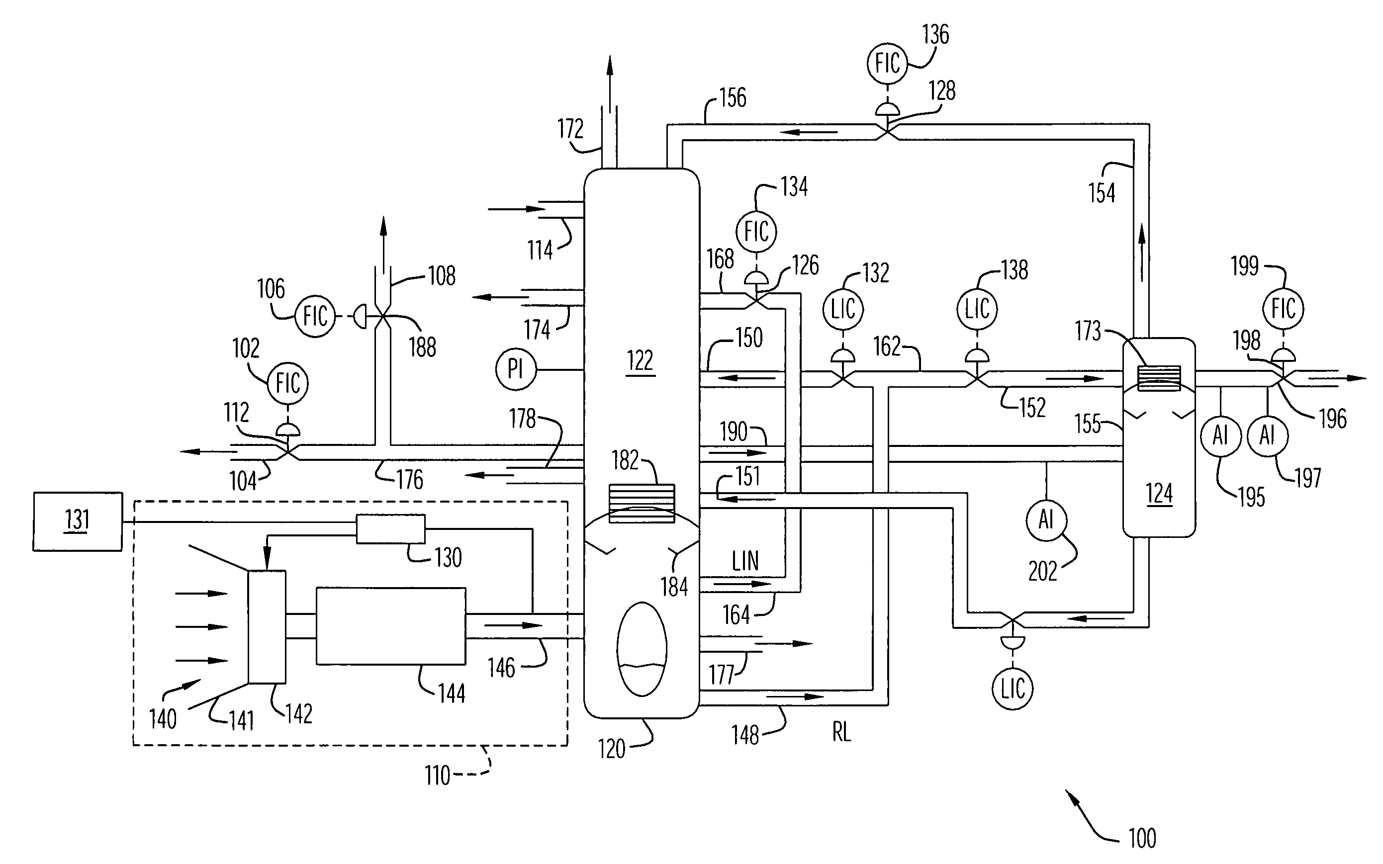
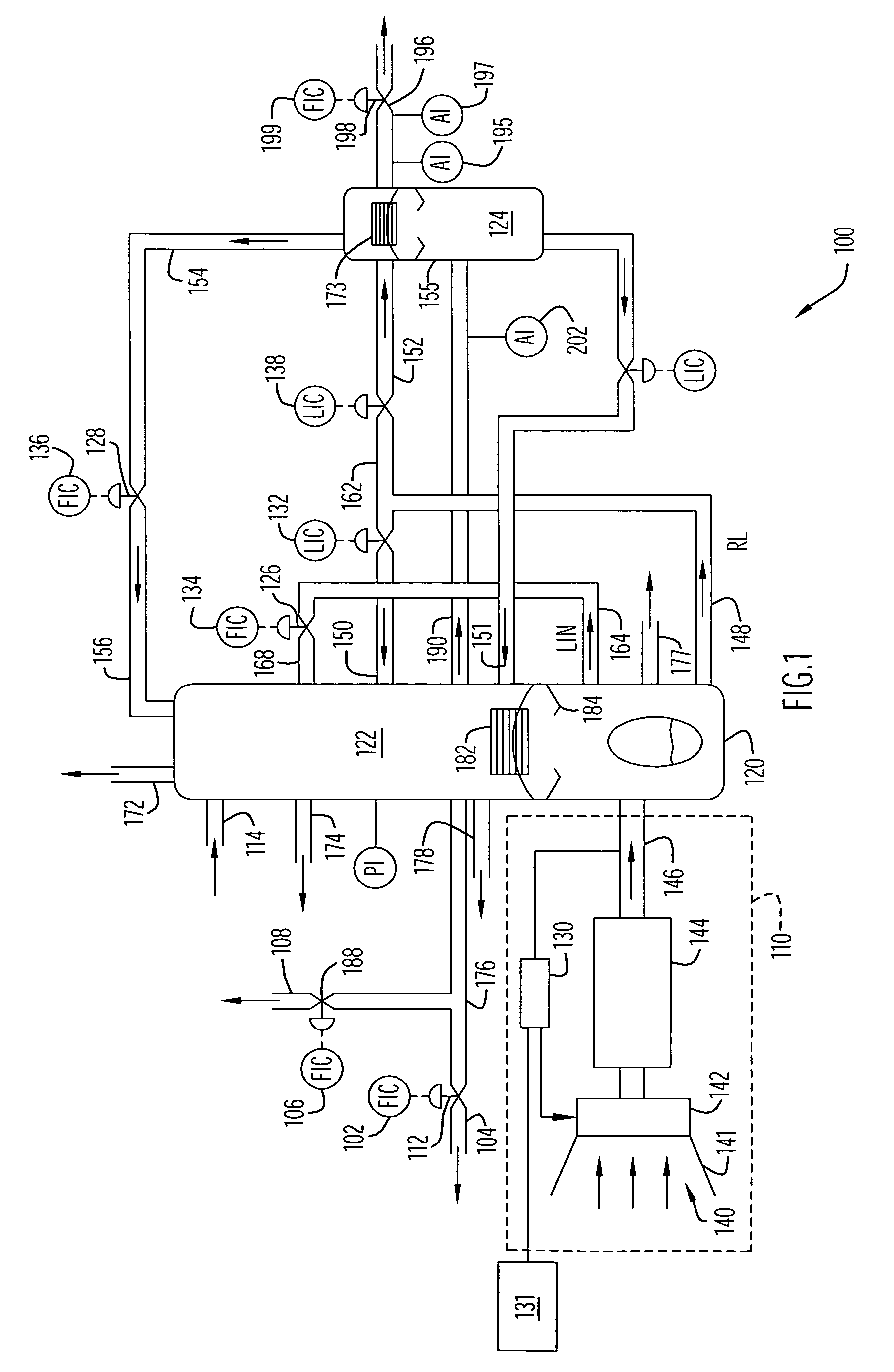
[0020]A typical system including an air separation unit (ASU) is disclosed in U.S. Pat. No. 6,622,521, which is herein incorporated by reference in its entirety. Referring to FIG. 1, an ASU can be configured such that atmospheric air is brought into the plant via an air input subsystem 110. The air input subsystem 110 may include an air inlet 140 with guide vanes 141, a filter 142, and an air treatment unit 144 including components such as an air compressor, a dryer, and a cooler. The dryer can further include one or more of molecular sieves, adsorption beds, desiccants, and front-end reversing exchangers. In an exemplary embodiment, the dryer uses a stream of waste nitrogen from another component within the air separation unit. The cooler, moreover, may comprise a high efficiency main heat exchanger. The treated flow of cool, dry, high-pressure air 146 is directed into a high-pressure, cryogenic distillation column 120. The composition of the high-pressure column is not limited, an...


PUM


Abstract

A cryogenic air separation system that optimizes the recovery of argon includes an air intake, a high-pressure distillation column, a low-pressure distillation column, a crude argon distillation column, and a controller that automatically controls the composition of the raw argon stream to decrease the concentration of oxygen in the stream while preventing the concentration of nitrogen in the crude argon stream from exceeding a selected value. In addition, the controller also controls the composition of the crude argon stream until an oxygen concentration of the crude argon stream reaches a selected value. The controller may include a multivariable predictive controller.

Description

CROSS-REFERENCE TO RELATED APPLICATIONS[0001]This application claims priority from U.S. Provisional Patent Application Ser. No. 60 / 509,139, entitled “MVPC-Based Air Separation Unit Argon Recovery Optimizer” and filed Oct. 6, 2003. The disclosure of the above-mentioned provisional application is incorporated herein by reference in its entirety.BACKGROUND OF INVENTION[0002]1. Field of Invention[0003]The present invention pertains to methods and systems for optimizing argon recovery in an air separation unit.[0004]2. Related Art[0005]Cryogenic Air Separation Units (ASUs) have been used to produce oxygen, nitrogen, and argon gases by cooling, liquefying, and distilling air. In a basic system, air is compressed and separated using high- and low-pressure cryogenic distillation columns. In the high-pressure column, nitrogen is separated from the air, creating oxygen rich liquid at the bottom and nitrogen rich liquid and vapor at the top. These products are extracted and some are fed separa...

Claims


Application Information

Patent Timeline
Patent Type & Authority Patents(United States)
IPC IPC(8): F25J3/00F25J3/04G05B13/04
CPCF25J3/04254F25J3/04412F25J3/04678F25J3/048F25J3/04848G05B13/048F25J2210/42Y10S62/924
Inventor SEIVER, DAVID S.SWAFFORD, SCOTT A.
Owner AIR LIQUIDE LARGE INDS U S LP
Why Eureka
Try Eureka