Electric circuit module

a technology of electric circuit module and lead wire, which is applied in the direction of basic electric elements, electrical apparatus construction details, lighting and heating apparatus, etc., can solve the problems of reducing the accuracy of lead wire placement, reducing the heat dissipation efficiency of the electrical device, and reducing the efficiency of heat dissipation quality, so as to improve the heat dissipation performance of the electric device, and stabilize the heat resistance resistan

Active Publication Date: 2007-04-17
HITACHI IND EQUIP SYST CO LTD
View PDF15 Cites 47 Cited by
  • Summary
  • Abstract
  • Description
  • Claims
  • Application Information

AI Technical Summary

Benefits of technology

[0018]The invention provides an electric circuit module capable of stabilizing heat resistance between a heat sink and an electric device and improving the heat radiating performance of the electric device. Also, the invention provides an electric circuit module capable of heightening the positional accuracy of an electric device and lead wires, which project from the electric device, and improving the assembling quality. Further, the invention provides an inexpensive electric circuit module capable of preventing coming-off of an electric device at the time of assembly.
[0021]Further, the invention has a feature in the provision of a member to prevent coming-off of an electric device from a fixture.
[0022]According to the invention, it is possible to stabilize heat resistance between a heat sink and an electric device and to improve the heat radiating performance of the electric device. Also, according to the invention, it is possible to heighten the positional accuracy of an electric device and lead wires, which project from the electric device, and to improve the assembling quality. Further, according to the invention, it is possible to prevent coming-off of an electric device at the time of assembly.

Problems solved by technology

Therefore, with the screwing configuration in the conventional packaging construction shown in FIG. 32, it is not possible to obtain an efficient and stable heat dissipating quality (heat resistance).
Also, the assembling quality is degraded by a decrease in accuracy to locate the lead wires.
Therefore, with the construction disclosed in JP-Y2-7-3674, it is believed that the material of the spring deteriorates to cause a decrease in pressing force and a stable heat dissipating quality cannot be obtained.
Also, with the construction disclosed in JP-Y2-7-3674, the lead wires are believed to be unnecessarily bent upon insertion.
Also, with the construction disclosed in JP-U-62-47140, it is not believed that it is possible to obtain an efficient and stable heat radiating quality (heat resistance).
With the construction disclosed in JP-A-2001-332670, since the spring material is thin and an area, in which the spring material is connected to the heat sink, is small, it is believed difficult to radiate heat from the spring member and the insulating material.

Method used


Image

  • Electric circuit module
  • Electric circuit module
  • Electric circuit module

Examples


Embodiment Construction

[0058]Embodiments of the invention will be described hereinafter with reference to the drawings.

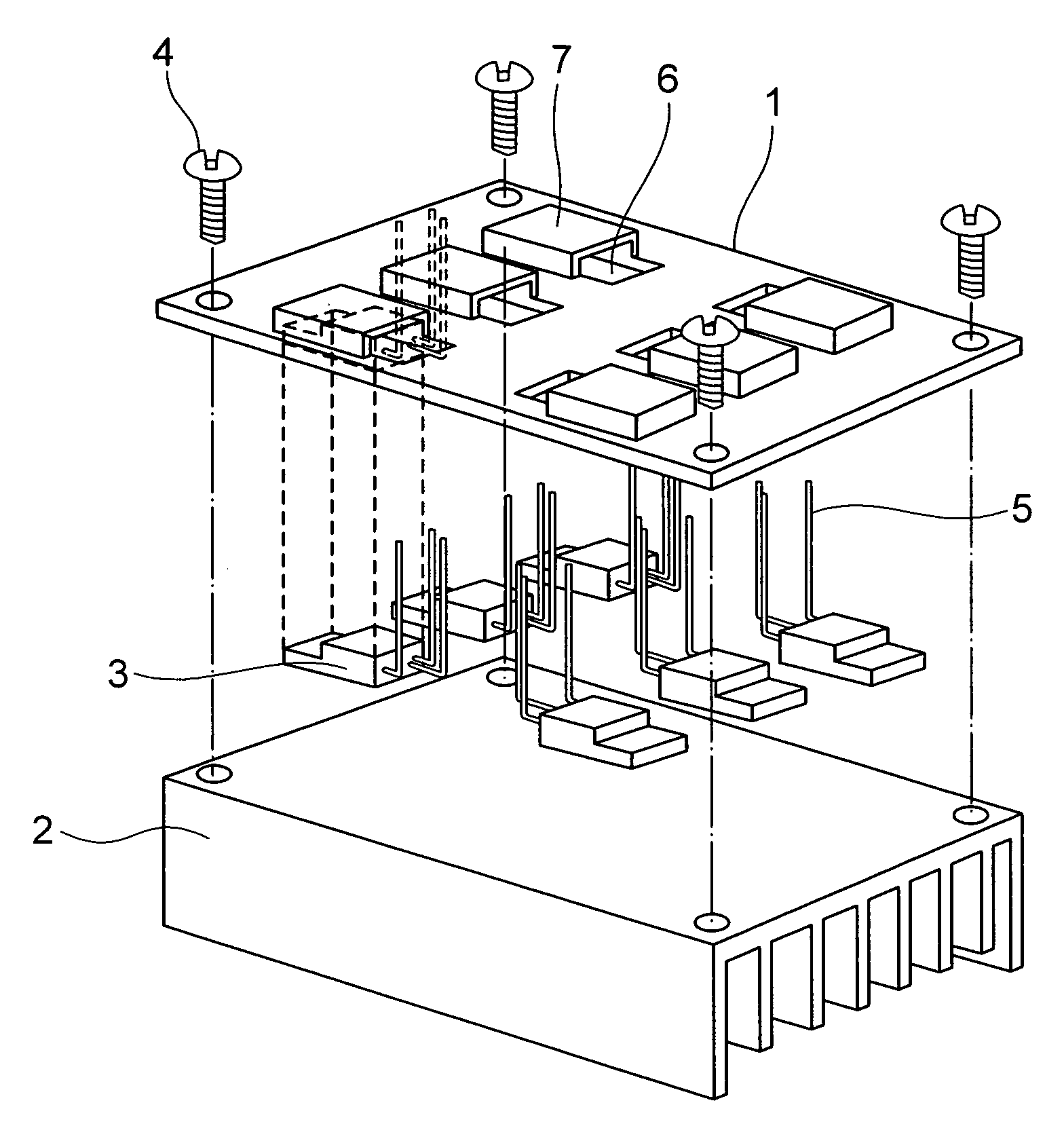
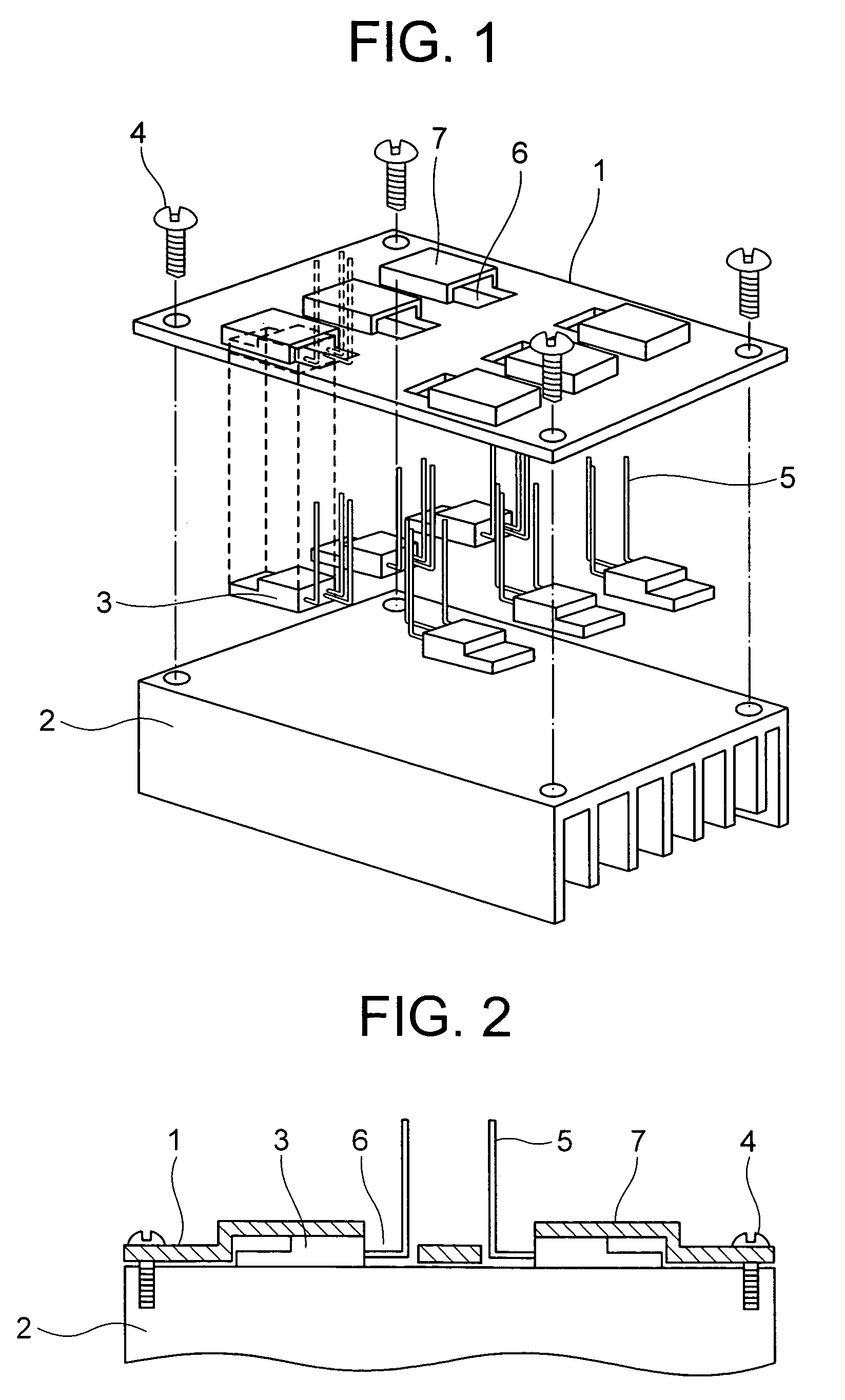
[0059]FIGS. 1 and 2 show a schematic configuration of a packaged construction of a 1st embodiment of an electric circuit module of the invention. A heat sink 2 shown in FIGS. 1 and 2 comprises a metal base formed of a material, such as copper, aluminum, etc., having an excellent thermal conductivity by means of molding or cutting. A plurality of fins are provided on a surface opposed to a mounting surface on which an electric device described later is mounted. The mounting surface of the heat sink 2 is provided at four corners thereof with threaded holes, into which clamp screws 4 are screwed. The clamp screws 4 are screwed into the threaded holes whereby a fixture 1 is fixed to the heat sink 2.

[0060]The fixture 1 is formed by using a metallic die to mold a resin or metal. In particular, inorganic powder filler typified by glass or silica is preferably mixed in the resin to enhance the st...


PUM


Abstract

An electric circuit module comprising: an electric device comprising an electric circuit to serve for passage and interruption of electric current, a packing material packing the electric circuit and a plurality of wiring members to electrically connect the electric circuit with an external circuit; and a heat sink to radiate heat from the electric device. The electric circuit module includes a fixture to fix the heat sink and the electric device together so that a heat radiating surface of the electric device comes into contact with the heat sink. The fixture is formed with a recess to accommodate therein a part of the electric device so that the heat radiating surface of the electric device is exposed from the fixture. When the electric device is fixed to the heat sink by the fixture, the heat radiating surface comes into contact with the heat sink.

Description

BACKGROUND OF THE INVENTION [0001]The present invention relates to an electric circuit module in which an electric device is mounted on a heat sink.[0002]An electric device, for example, a power semiconductor, is fixed to a copper plate by solder and the electric device together with lead wires for connection to an external circuit is encapsulated by a resin packing material, which is typified by epoxy resins, in a transfer molding method. Power semiconductors generate heat when applying electric current. The generated heat is dissipated to the outside through the copper plate or the packing material. Such a conventional power semiconductor constructed in this manner is mounted on a heat sink as shown in FIG. 32. More specifically, a screw is inserted through a through-hole provided on the packing material, and the screw is threadedly attached to the heat sink whereby the power semiconductor is fixed to the heat sink. Thereby, the power semiconductor is pressed against the heat sink...

Claims


Application Information

Patent Timeline
Patent Type & Authority Patents(United States)
IPC IPC(8): H05K7/20H01L23/367H01L23/40H01L25/07H01L25/11H01L25/18
CPCH01L23/4006H01L25/115H01L2023/4031H01L2023/405H01L2023/4081H01L2224/48137H01L2224/48091H01L2224/48247H01L2224/73265H01L2023/4087H01L2924/00014
Inventor NAKATSU, KINYATAKATA, NAOKIHIROTA, MASAYUKIIBORI, SATOSHIKAMEZAWA, TOMOYA
Owner HITACHI IND EQUIP SYST CO LTD
Why Eureka
Try Eureka