Exhaust gas purifying method and exhaust gas purifying system

a technology of exhaust gas purification and purification method, which is applied in the direction of machines/engines, electrical control, separation processes, etc., can solve the problems of deteriorating nox purification efficiency, inability to burn nox components in pm by catalyst alone, and inability to improve an engine. , to achieve the effect of reducing fuel consumption, simplifying the system, and reducing fuel consumption

Active Publication Date: 2007-04-24
ISUZU MOTORS LTD
View PDF9 Cites 42 Cited by
  • Summary
  • Abstract
  • Description
  • Claims
  • Application Information

AI Technical Summary

Benefits of technology

[0014]It is an object of the present invention to provide an exhaust gas purifying method and an exhaust gas purifying system capable of efficiently purging the sulfur accumulated in a NOx occluding reduction type catalyst, while preventing fuel consumption from deteriorating and preventing NOx, HC, and CO from being discharged into atmosphere, in an exhaust gas purifying system constituted by combining the NOx purifying function of a NOx occluding reduction type catalyst with the PM purifying function of a DPF.
[0023]Particularly, by making a NOx occluding reduction type catalyst support on the DPF with the catalyst to integrate them, it is possible to simultaneously purify PM and NOx. That is, when exhaust gas is in a lean air-fuel ratio state in lean burn, NOx is occluded in the NOx occluding material of the catalyst. PM is oxidized by the active oxygen (O*) and O2 in the exhaust gas, which are generated at the time of NOx occlusion. Moreover, when the exhaust gas is in a rich air-fuel ratio state through theoretical air-fuel-ratio combustion or over-rich air-fuel-ratio combustion for regenerating the NOx occlusion capacity, NOx is discharged from the NOx occluding material and even if the quantity of O2 in the exhaust gas is small, PM is oxidized in the catalyst by the active oxygen (O*) generated at the time of reduction of NOx. According to this constitution, because the NOx occluding reduction type catalyst and the catalyst-carrying DPF are integrated, it is possible to downsize and simplify the system.
[0024]Furthermore, when the DPF and the NOx occluding reduction type catalyst are separated from each other, even if the DPF is set at the downstream side of the NOx occluding reduction type catalyst, the sulfur purge of the NOx occluding reduction type catalyst is performed after raising the temperature of exhaust gas to remove PM from the DPF. Therefore, it is possible to obtain an advantage of reducing fuel consumption. However, when the DPF is set at the upstream side of the NOx occluding reduction type catalyst, the exothermic effect due to burning of the PM collected by the DPF can be also used for the exhaust gas temperature rise for performing the sulfur purge of the NOx occluding reduction type catalyst. Therefore, an advantage of further reducing fuel consumption can be obtained. Thus, when the DPF and the NOx occluding reduction type catalyst are separated from each other, it is more preferable to set the DPF at the upstream side of the NOx occluding reduction type catalyst.
[0025]According to the exhaust gas purifying method and the exhaust gas purifying system of the present invention, regeneration control of the DPF is performed and thereafter the sulfur purge control of the NOx occluding reduction type catalyst is performed. Therefore, it is possible to perform the sulfur purge of the NOx occluding reduction type catalyst by using the raise of the exhaust gas temperature and the temperature of the NOx occluding reduction type catalyst when performing the regeneration control of the DPF for forcibly burning collected PM. Therefore, it is possible to decrease the time and fuel consumption relating to the raise of the temperature of the NOx occluding reduction type catalyst. Consequently, it is possible to efficiently and effectively purge sulfur while preventing the fuel consumption from deteriorating and preventing NOx, HC, and CO from being discharged to the atmosphere.

Problems solved by technology

Thus, only improvement of an engine cannot manage a restriction value for the enforcement of the restriction.
However, when using the NOx occluding reduction type catalyst, it is impossible to burn a soot component in PM by the catalyst alone.
The NOx occluding reduction type catalyst has a problem in that sulfur in fuel is accumulated in the NOx occluding material, and the NOx purifying efficiency is deteriorated as the operation of the engine continues.
However, the sulfur purge for recovering the NOx occluding function of the catalyst by increasing the quantity of sulfur purge has the following problems.
Because the oxygen concentration in exhaust gas is very low under a rich air-fuel-ratio state, the time required to raise the temperature of the catalyst up to a temperature at which the sulfur purge can be made becomes very long.
Therefore, fuel consumption is deteriorated.
However, when performing a dense rich state operation, fuel consumption is extremely deteriorated.
Moreover, a problem of slip of HC or CO occurs that HC or CO is generated in a large quantity and some of HC or CO is discharge into atmosphere.
However, in a state where an exhaust gas temperature is low and clogging of the DPF progresses, exhaust gas temperature raising control such as an intake-air throttling is performed to temporarily raise the temperature of exhaust gas in order to burn and remove the collected PM.

Method used


Image

  • Exhaust gas purifying method and exhaust gas purifying system
  • Exhaust gas purifying method and exhaust gas purifying system
  • Exhaust gas purifying method and exhaust gas purifying system

Examples


Embodiment Construction

[0033]An exhaust gas purifying method and an exhaust gas purifying systems of embodiments of the present invention are described below by referring to the accompanying drawings.

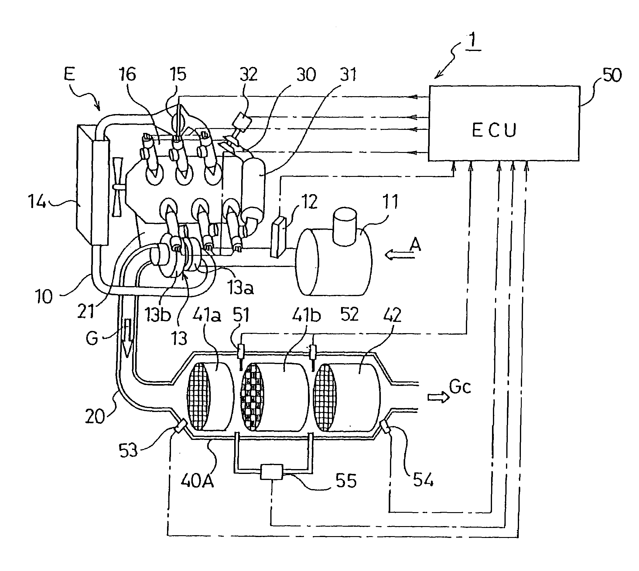
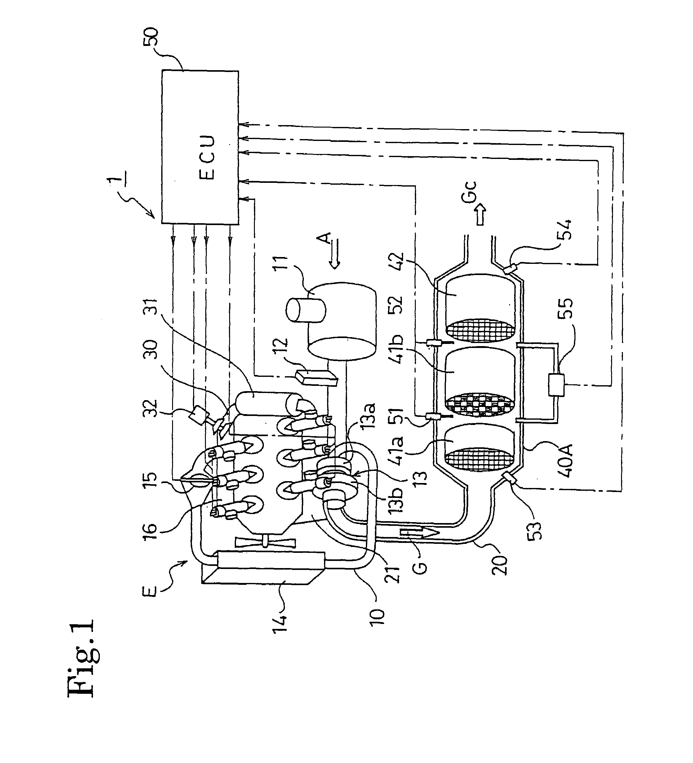
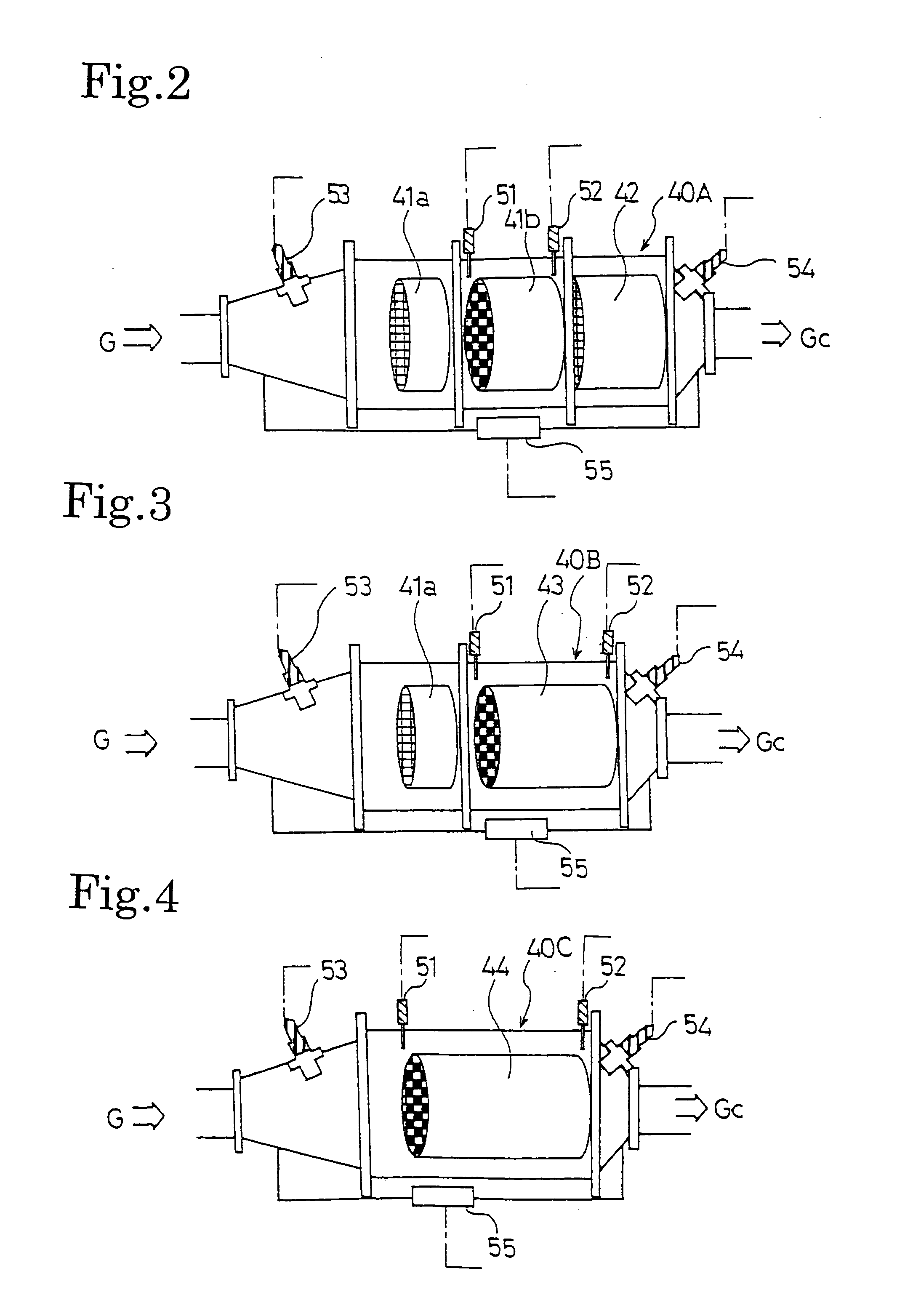
[0034]FIG. 1 shows a constitution of an exhaust gas purifying system 1 of an embodiment. The exhaust gas purifying system 1 is constituted of including an exhaust passage 20 of an exhaust gas purifying apparatus 40A in an engine (internal combustion engine) E. The exhaust gas purifying apparatus 40A is constituted providing with an oxidation catalyst (DOC) 41a, a DPF 41b, and a NOx occluding reduction type catalyst converter 42 in order from the upstream side. Moreover, a continuously regenerating type DPF 41 is constituted of the upstream-side oxidation catalyst 41a and the downstream-side DPF 41b.

[0035]The oxidation catalyst 41a is formed by a monolith catalyst having a lot of polygonal cells formed by a structural material of cordierite, SiC, or stainless steel. A catalyst coat layer occupying the surface...


PUM

PropertyMeasurementUnit
temperatureaaaaaaaaaa

Abstract

To provide an exhaust gas purifying method and an exhaust gas purifying system capable of efficiently purging the sulfur accumulated in a NOx occluding reduction type catalyst, while preventing fuel consumption from deteriorating and preventing NOx, HC, and CO from being discharged into the atmosphere, in an exhaust gas purifying system constituted by combining a NOx purifying function by the NOx occluding reduction type catalyst with a PM purifying function by a DPF. In an exhaust gas purifying system (1) for performing NOx purification by a NOx occluding reduction type catalyst (42) and PM purification by an DPF (41), it is judged whether sulfur purge of the NOx occluding reduction type catalyst is required and when it is judged that the sulfur purge is required, it is further judged whether the PM quantity (PMst) accumulated in the DPF (41b) exceeds a predetermined judgment value (PMst0), and when the PM quantity (PMst) exceeds the judgment value (PMst0), sulfur purge control is performed after performing the DPF regeneration control.

Description

BACKGROUND OF THE INVENTION[0001]The present invention relates to an exhaust gas purifying method and an exhaust gas purifying system for purifying NOx by a NOx occluding reduction type catalyst and purifying PM by a DPF.[0002]Legal restriction on discharge quantities of NOx (nitrogen oxide) and particulate matter (hereafter referred to as PM) is enforced year by year together with legal restriction on discharge quantities of CO (carbon monoxide) and HC (carbon hydride). Thus, only improvement of an engine cannot manage a restriction value for the enforcement of the restriction. Therefore, a technique is adopted which reduces these matters discharged from an engine by mounting an exhaust gas control system.[0003]Moreover, many NOx purifying catalysts are developed for NOx and a filter referred to as a diesel particulate filter (hereafter referred to as DPF) is developed for the PM.[0004]A NOx occluding reduction type catalyst is one of the NOx purifying catalysts. In the NOx occludi...

Claims


Application Information

Patent Timeline
Patent Type & Authority Patents(United States)
IPC IPC(8): F01N3/00F01N3/02B01D46/42B01D53/94F01N3/023F01N3/08F01N3/18F01N3/20F01N3/24F01N3/28F02D41/02
CPCF02D41/028F02D41/029F02D2200/0812
Inventor NAGAOKA, DAIJIGABE, MASASHI
Owner ISUZU MOTORS LTD
Why Eureka
Try Eureka