

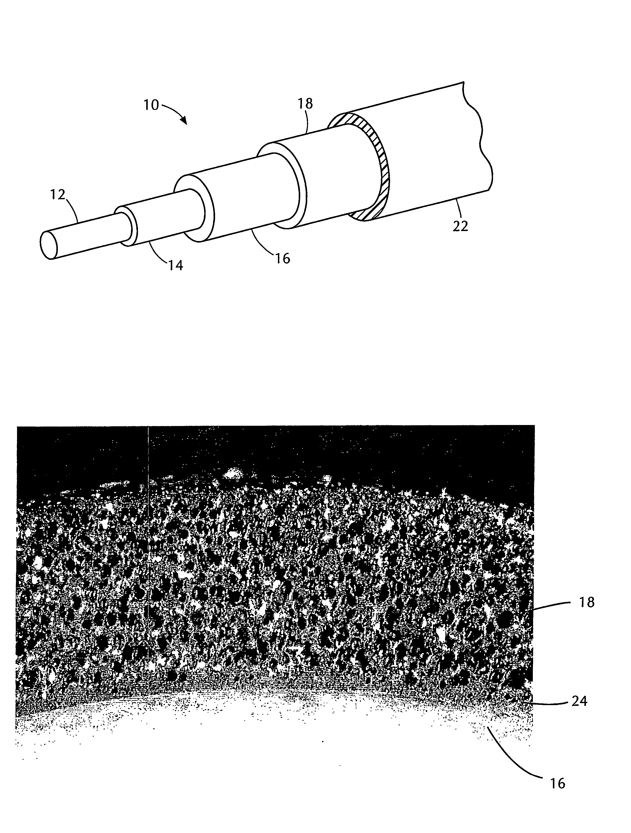
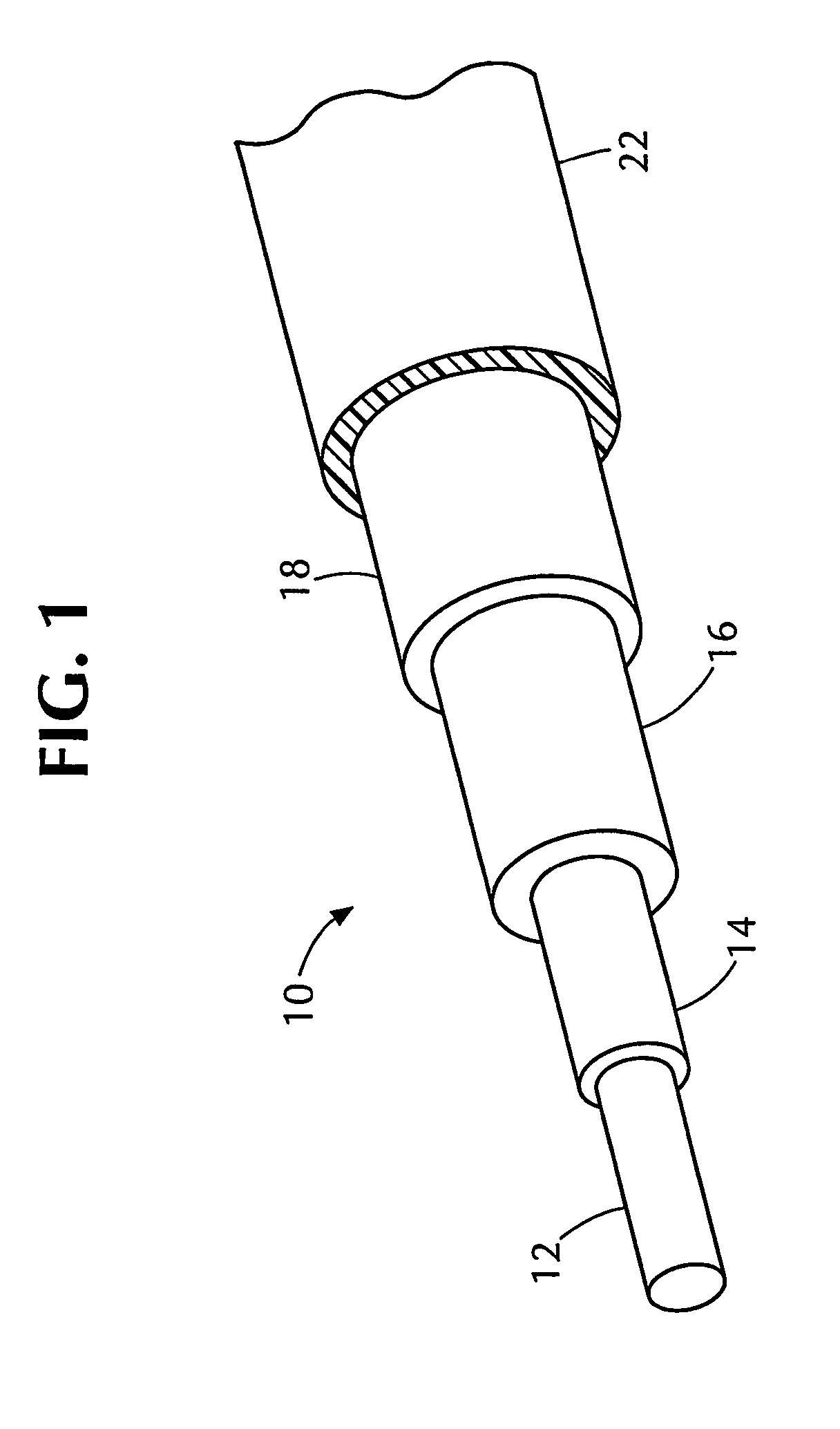
Electrical cable with foamed semiconductive insulation shield
a semi-conductive insulation shield and electrical cable technology, applied in the field of semi-conductive insulation shields and electrical cables, can solve the problems of reducing the likelihood of failure, and achieve the effect of less voids, reduced failure probability, and easy filling
- Summary
- Abstract
- Description
- Claims
- Application Information
AI Technical Summary
Benefits of technology
Problems solved by technology
Method used
Image

Examples
examples 1 – 2
EXAMPLES 1–2
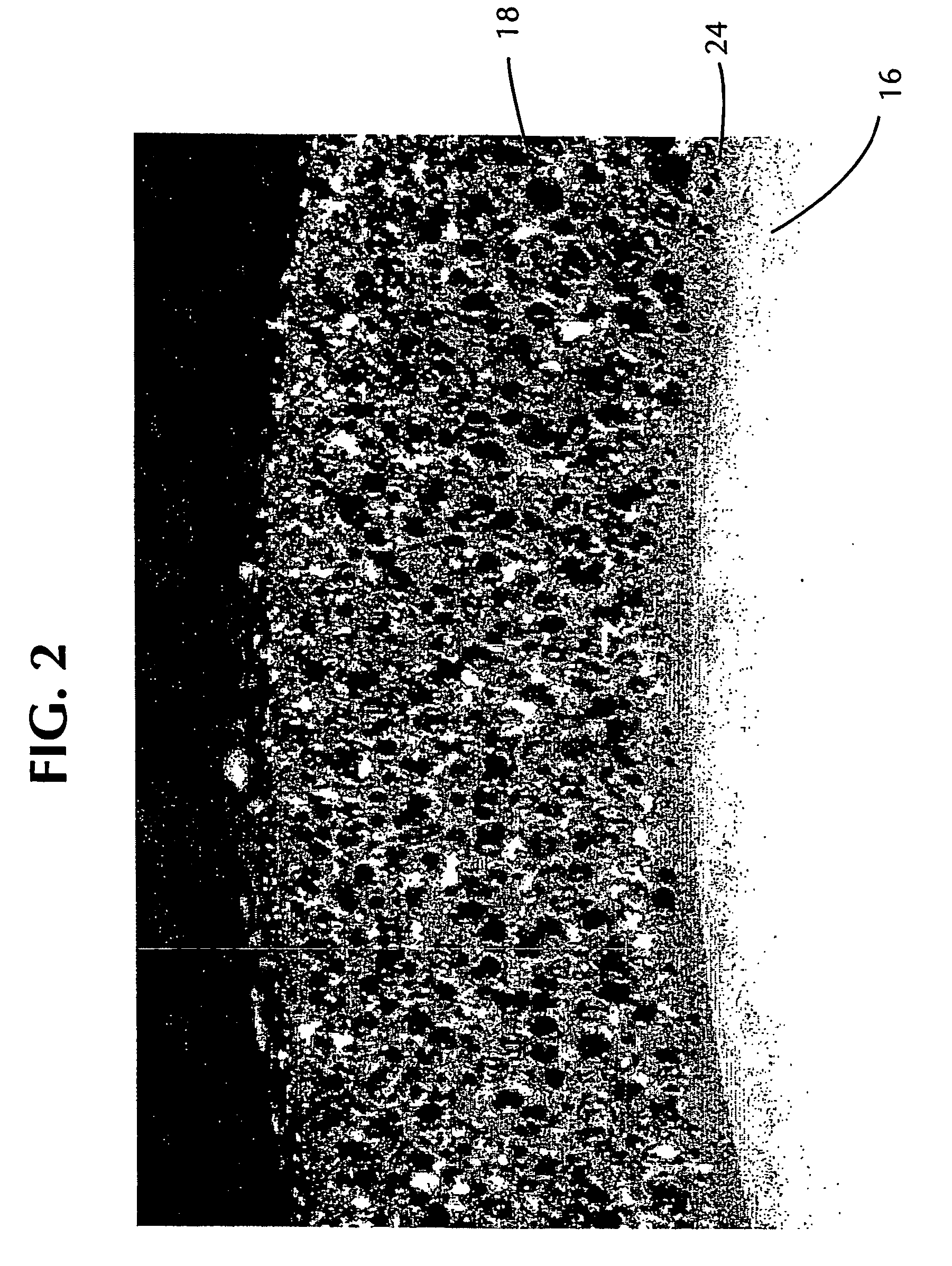
[0037]Semiconductive insulation shields according to the present invention, employing exothermic chemical foaming agents, were extruded along with the conductor shield and insulation layer onto No. 1 / 0 American Wire Gauge (AWG) conductor and foamed and crosslinked in a nitrogen gas (N2) environment at elevated temperature and pressure. Table 1 gives the formulations and process conditions for Examples 1–2.
[0038]
TABLE 1CV CuringFoamingInsulation ShieldProcessLinespeedExampleAgent / TypeCompositionInsulationConditions(fpm)1Celogen OT100 pphr EVA Base ResinTRXLPEN2 at 135 psi and35Exothermicand additives (carbon black,tube zoneDecomp. Temp:chemical crosslinking agent,Temperatures:175° C.–220° C.processing aids); 2.52 pphr750 / 750 / 750 / 725 / (347° F.–428° F.)Celogen OT 1.05 pphr BIK725 / 700° F.OT catalyst2Hydrocerol96% by weight EVA BaseEPRN2 at 135 psi and54CT1376Resin and additives (carbontube zoneDecomp. Temp:black, chemical crosslinkingTemperatures:190° C. (374° F.)agent, proce...
example 3
[0045]A semiconductive insulation shield according to the present invention, employing a hybrid exothermic / endothermic chemical foaming agent, was extruded along with a conductor shield and an insulation layer onto No. 1 / 0 AWG conductor (approximate equivalent of 53.49 mm2 metric conductor), and foamed and crosslinked in a steam environment at elevated temperature and pressure. Table 2 gives the formulations and process conditions for Example 3.
[0046]
TABLE 2CV CuringFoamingInsulation ShieldProcessLinespeedExampleAgent / TypeCompositionInsulationConditions(fpm)3Hydrocerol CT127196% by weight EVAEPRSteam at 203 psi6.6Hybrid:Base Resin andand tubeEndothermic / additives (carbontemperatureExothermicblack, chemicalzones 1–4 atDecomp. Temp:crosslinking agent,715° F.190° C.processing aids); 4%by weight CT 1271(70% Active contentin EVA carrier)
[0047]The foamed insulation shield of Example 3 achieved a density reduction of about 28% and had very good surface quality. When tested for partial disc...
example 4
[0049]A semiconductive insulation shield according to the present invention, employing a hybrid exothermic / endothermic chemical foaming agent, was extruded along with a conductor shield and insulation layer onto No. 1 / 0 AWG conductor, and foamed and crosslinked in a N2 environment at elevated temperature and pressure. Table 3 gives the formulations and process conditions for Example 4.
[0050]
TABLE 3Foaming Agent / Insulation ShieldCV Curing ProcessLinespeedExampleTypeCompositionInsulationConditions(fpm)4Hydrocerol96% by weight EVAEPRN2 at 135 psi and35CT1271Base Resin andtube zoneHybrid:additives (carbontemperatureEndothermic / black, chemical725 / 725 / 700 / 700 / 675 / Exothermiccrosslinking agent,650° F.Decomp. Temp:processing aids); 4%190° C.by weight CT1271(70% Active content inEVA carrier)
[0051]The foamed insulation shield of Example 4 achieved a density reduction of about 32%. The cable of Example 4 was tested according to AEIC requirements and successfully complied with those requirements...
PUM
| Property | Measurement | Unit |
|---|---|---|
| pressure | aaaaa | aaaaa |
| volume resistivity | aaaaa | aaaaa |
| length | aaaaa | aaaaa |
Abstract
Description
Claims
Application Information