
Methods and apparatuses for homogenizing light

Active Publication Date: 2007-05-01
RESONETICS
View PDF7 Cites 7 Cited by
  • Summary
  • Abstract
  • Description
  • Claims
  • Application Information

AI Technical Summary

Benefits of technology

[0014]Accordingly, embodiments of the present invention utilize the advantages of a fly's-eye array to homogenize one dimension / axis (e.g., a long axis) of an illumination field and the advantage of the kaleidoscope to homogenize another dimension / axis (e.g., a short axis) of the illumination field, to produce a homogenized illumination field in at least two dimensions in a cost-effective and compact device. Moreover, some embodiments of the present invention perform homogenization for two axes simultaneously in the same physical space.
[0021]A particular advantage of some embodiments of the invention is that a workpiece may be scanned with a minimum number of scans (or swathes). Adjacent scans create stitching concerns at the overlap between two adjacent scans which degrades quality of the process. Moreover, some processes (such as silicon annealing, for example) are so sensitive to light dosage, that they may even prohibit any overlap between adjacent scans. So, process quality is enhanced if a part can be processed in the least amount of scans, or even one scan (rather than multiple scans).

Problems solved by technology

The prior art devices encounter difficulties creating simple and cost-effective high aspect ratio homogenized fields of illumination.
Optical parts with such high aspect ratios are extremely difficult to manufacture.
Although such mechanical aspect ratios can be moderated by introducing an anamorphic imaging device between the fly's eye and the mask, such an addition increases complexity to the system.
It becomes obvious to one of skill in the art that this design becomes prohibitively expensive and impractical to fabricate for this high aspect ratio beam.
Other problems exist for kaleidoscope homogenizers.
It becomes obvious to one of ordinary skill in the art, that for a high aspect ratio homogenizer, such a kaleidoscope design becomes impractical to implement and extremely cost prohibitive.
Such homogenization system results in poor light utilization efficiency.
In other cases, the full length cannot be accommodated, because the long axis of the field is not sufficiently uniform.
This truncation lowers efficiency of the beam delivery system.

Method used


Image

  • Methods and apparatuses for homogenizing light
  • Methods and apparatuses for homogenizing light
  • Methods and apparatuses for homogenizing light

Examples


Embodiment Construction

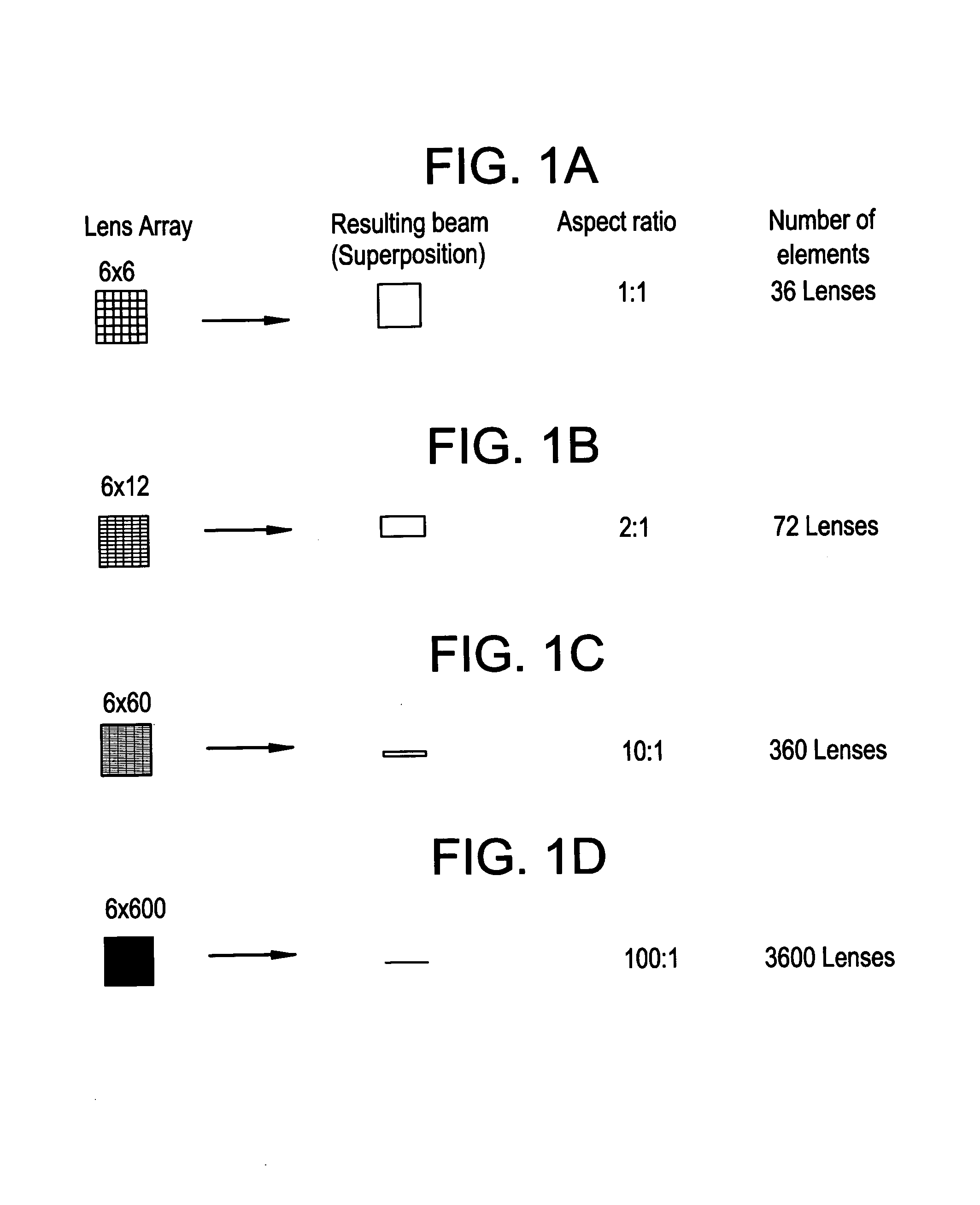
[0036]One purpose of the present invention is to generate, for example, a long rectangular laser illumination field homogenized both in a long (wide) direction (d1) and in a short (narrow) direction (d2), wherein (d1):(d2) is at least 5:1 (for example). Accordingly, some embodiments of the invention include an apparatus that synthesizes concepts from kaleidoscope and fly's eye homogenizer techniques to produce such a homogenized field. For example, in some embodiments, a one-dimensional fly's eye homogenizer is used to homogenize the laser beam in the long direction (d1) of the rectangular field and a one-dimensional kaleidoscope homogenizer is used to homogenize the beam in the short direction (d2) of the rectangular field.

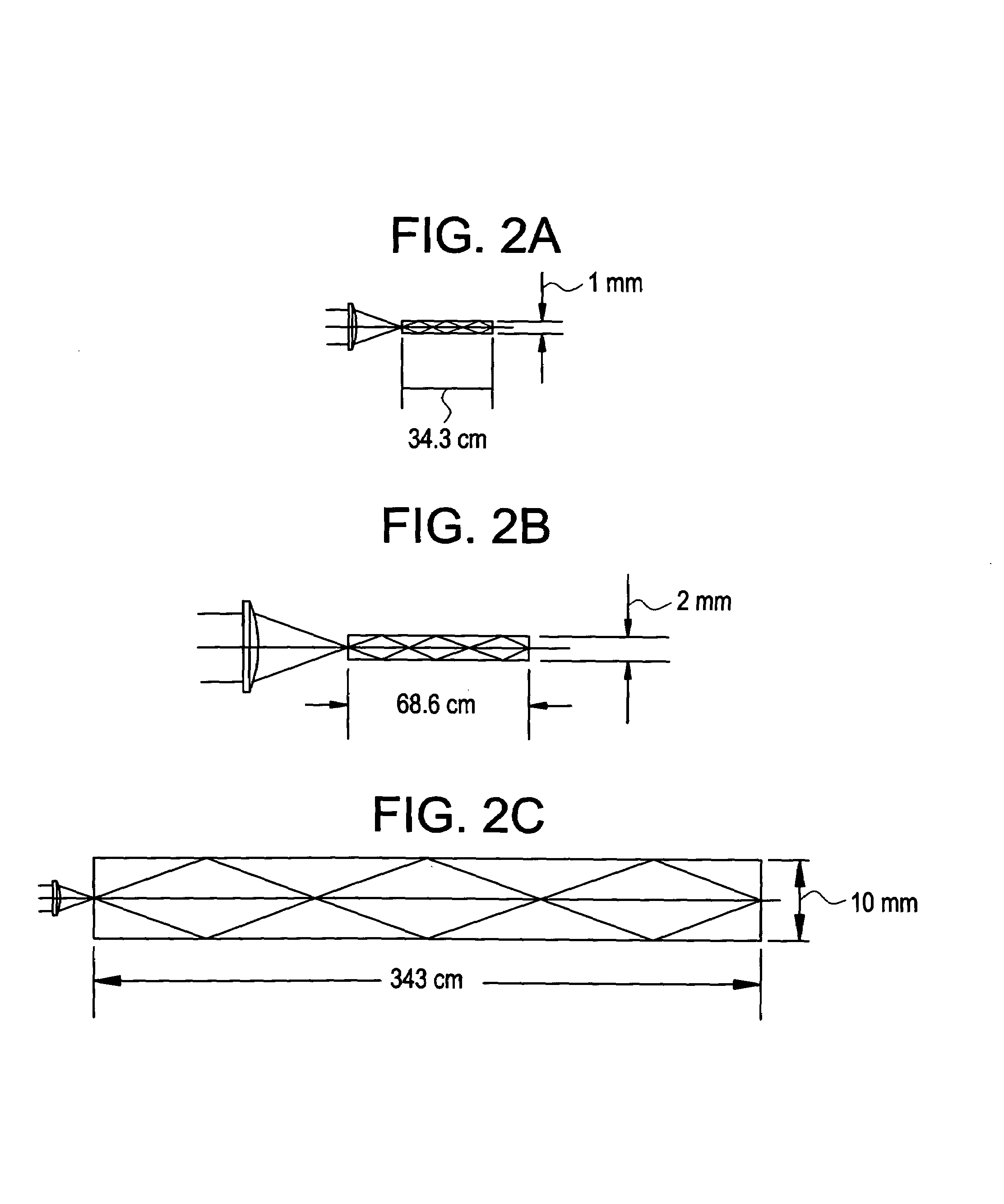
[0037]To the first order, the aspect ratio for such a rectangular illumination field may be determined in the following manner. The long dimension may equal the distance from the fly's-eye homogenizer focus to mask, multiplied by the result of dividing the width ...


PUM

PropertyMeasurementUnit
Volumeaaaaaaaaaa
Ratioaaaaaaaaaa
Dimensionaaaaaaaaaa

Abstract

Embodiments of the present invention are directed to an illuminating optical device for forming a field of illumination. The optical device includes a first one-dimensional homogenizer positioned to homogenize a first dimension / axis of the field of illumination and a second one-dimensional homogenizer positioned to homogenize a second dimension / axis of the field of illumination.

Description

CLAIM TO PRIORITY[0001]The present invention claims priority under 35 U.S.C. §119(e) of U.S. provisional patent application No. 60 / 468,511, filed May 7, 2003, the entire disclosure of which is herein incorporated by reference.FIELD OF THE INVENTION[0002]The present invention is directed to the field of optics. Specifically, the present invention is directed to light homogenizers, and more particularly, to light homogenizers for applications which may require a high aspect ratio fields (e.g., long line light homogenizers). In the context of this invention, the term light is defined as electromagnetic radiation from X-ray to Infrared wavelengths.BACKGROUND OF THE INVENTION[0003]To perform laser or photon material processing it is often desirable to create a field of uniform irradiation so that the process will produce consistent results within an area of a homogenous optical field. An unrequited goal of current technology is to create a beam homogenizer device capable of transforming ...

Claims


Application Information

Patent Timeline
IPC IPC(8): F21S8/00G02B27/09
CPCG02B27/09G02B27/0927G02B27/0961G02B27/0966G02B27/0983G03F7/70066G03F7/70075
Inventor BROUDE, SERGEY V.HOLBROOK, DAVID S.MILLER, PASCAL
Owner RESONETICS
Learn More