Magnetic floating device
a floating device and magnetic technology, applied in the field of magnetic floating devices, can solve the problems of inability to operate normally, disadvantages of smaller floating force, etc., and achieve the effects of reducing the force in unwanted directions, and reducing the size and weight of the devi
- Summary
- Abstract
- Description
- Claims
- Application Information
AI Technical Summary
Benefits of technology
Problems solved by technology
Method used
Image

Examples
embodiment 1
[Embodiment 1]
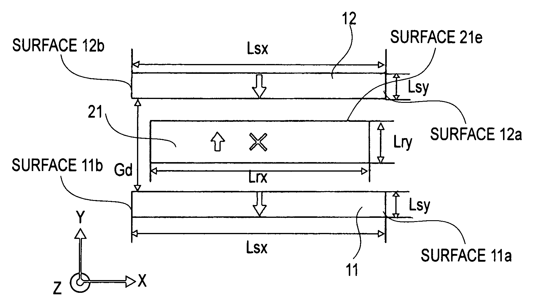
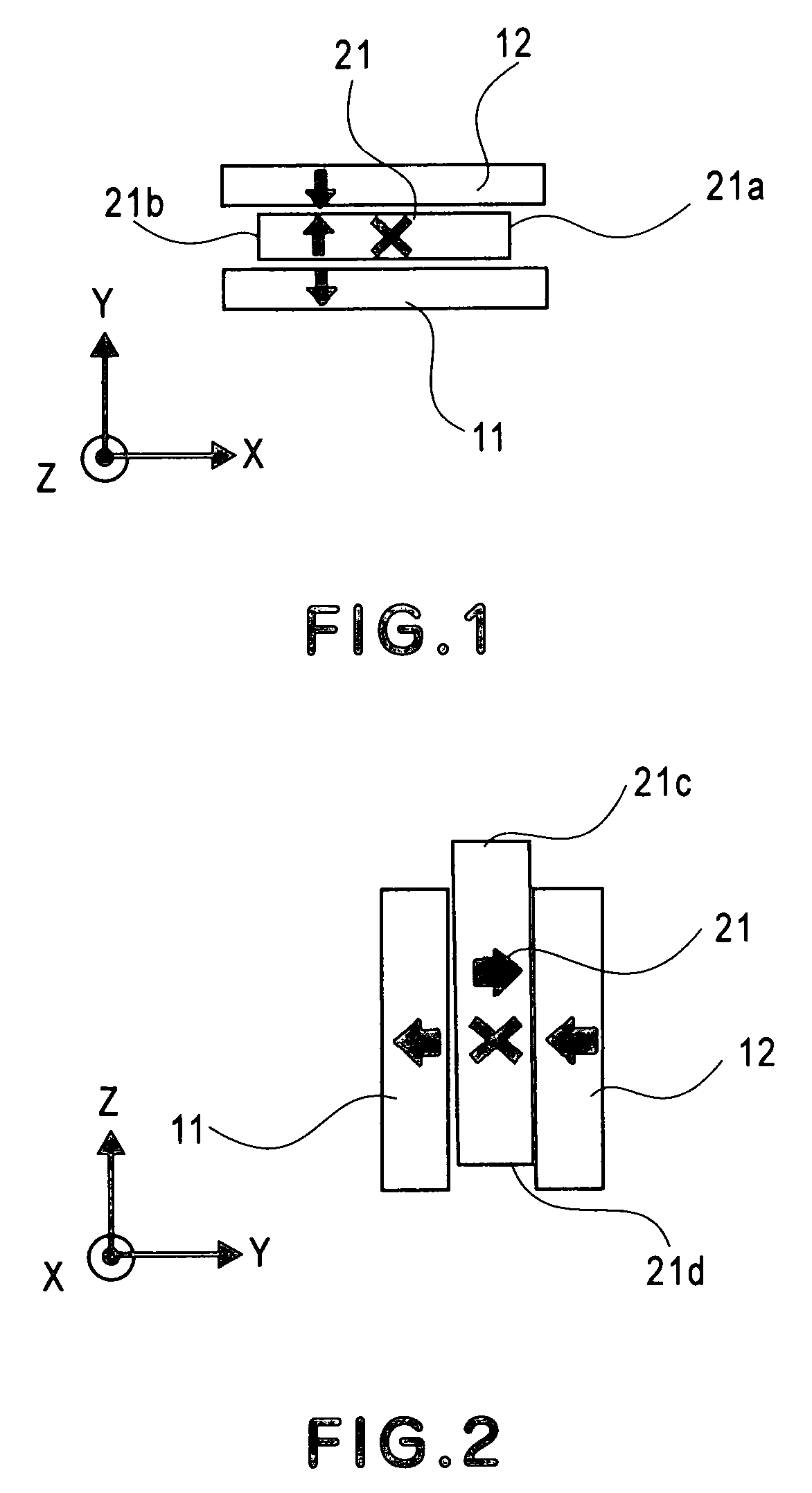
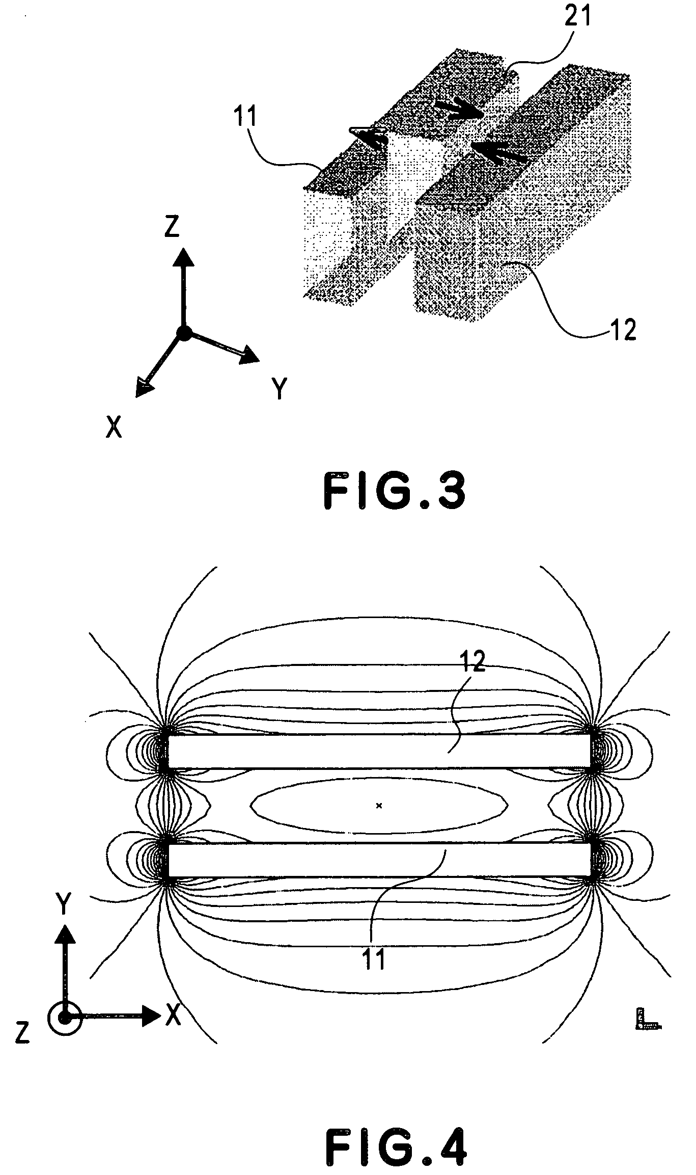
[0044]FIGS. 1–3 show a magnetic floating device according to a first embodiment of the present invention. FIG. 1 is an X-Y plan view, FIG. 2 is a Y-Z plan view, and FIG. 3 is a perspective view. In the magnetic floating device of FIGS. 1–3, an X-axis direction corresponds to a lengthwise direction, and a Y-axis direction corresponds to a polarization direction of a magnet. A Z-axis direction corresponds to the floating direction. The lengthwise direction intersects with the polarization direction and the floating direction perpendicularly. Arrows in the drawings depict the directions of magnetization of magnets. A symbol x denotes the origin which is the center of the magnetic floating device. Denoted at 11 and 12 are fixed magnets, and their orientation of magnetization is put on in the same direction along the Y-axis direction, as shown in FIG. 1.
[0045]Denoted at 21 is a movable magnet, and its orientation of magnetization is put on in an opposite direction to that o...
embodiment 2
[Embodiment 2]
[0052]FIG. 6 shows a magnetic floating device according to a second embodiment of the present invention, and it corresponds to FIG. 5 of the first embodiment. In the first embodiment, although the lateral shift force can be made smaller, the floating force decreases as well. The second embodiment is an example wherein the floating force is made larger by making the lateral shift force smaller. The range B in FIG. 6 is a range that extends from an extreme value position at the end edge of the fixed magnet of the By component, at the magnetic floating device center (Y=0), to an extreme value position at an end edge of the fixed magnet of the By component at the opposing surface (Y=10 [mm]) of the movable magnet 21, opposed to the fixed magnet 12. The wording “polarization direction center of a magnetic floating device” to be referred to later in the claims attached to this specification corresponds to Y=0 in FIG. 6.
[0053]Where the end portion of the movable magnet 21 is ...
embodiment 3
[Embodiment 3]
[0054]A third embodiment of the present invention is an example wherein, in the Y-Z plane of FIG. 2, magnetization of a movable magnet 21 is cleared and a Z-axis direction distribution of Y-axis magnetic flux density (By) component in the X=0 section, to be produced by fixed magnets 11 and 12, is formed in the manner as shown in FIG. 7. FIG. 8 is a graph showing the Z-axis direction distribution of the By component at X=0 in FIG. 7. The axis of abscissa denotes Z-axis coordinate, and the axis of ordinate denotes By component. In FIG. 8, Y=0 depicts the By-X characteristic at the center of the magnetic floating device, and Y=10 [mm] depicts the By-X characteristic at the upper surface (opposing surface 21e being opposed to the fixed magnet 12) in FIG. 8 of the movable magnet 21. The integrated value is a value obtainable by integrating the By-Z characteristic with respect to the Y axis. The extreme value position of the integrated Y-axis magnetic flux density By is defi...
PUM
| Property | Measurement | Unit |
|---|---|---|
| magnetic force | aaaaa | aaaaa |
| magnetic | aaaaa | aaaaa |
| magnetic flux density | aaaaa | aaaaa |
Abstract
Description
Claims
Application Information
 - R&D
- Intellectual Property
- Life Sciences
- Materials
- Tech Scout
- Unparalleled Data Quality
- Higher Quality Content
- 60% Fewer Hallucinations
Browse by: Latest US Patents, China's latest patents, Technical Efficacy Thesaurus, Application Domain, Technology Topic, Popular Technical Reports.
© 2025 PatSnap. All rights reserved.Legal|Privacy policy|Modern Slavery Act Transparency Statement|Sitemap|About US| Contact US: help@patsnap.com