Electrical discharge machine power supply

a technology of electric discharge machine and power supply, which is applied in the direction of electrical-based machining apparatus, metal-working apparatus, manufacturing tools, etc., can solve the problems of long machining time, increased machining cost, and increased machining cost, so as to reduce the ionization of working fluid, shorten the application time of voltage pulse to the tool electrode, and improve the effect of machining efficiency

Inactive Publication Date: 2007-05-08
PANASONIC CORP
View PDF9 Cites 4 Cited by
  • Summary
  • Abstract
  • Description
  • Claims
  • Application Information

AI Technical Summary

Benefits of technology

[0014]According to the present invention, the electrical discharge machining apparatus includes the charging switching element for switching the charging circuit that charges the capacitor and the charge regulating switching element for switching the charge regulating circuit. Switching each of the two switching elements can utilize a short rise time of the switching element to generate the voltage pulse whose pulse duration is very narrow. Therefore, because an applying time of the voltage pulse to the tool electrode can be shortened, ionization of the working fluid can be suppressed and machining efficiency can be improved.
[0015]In the electrical discharge machining apparatus according to the present invention, a state between the tool electrode and the work is determined, and a duty ratio of a voltage pulse to be applied is controlled depending on the determined state. Therefore, the duty ratio of the voltage pulse can appropriately be set on the basis of the state such as an electrical discharging state, abnormal electrical discharging state, ion conducting state, and short circuiting state to suppress the ionization of the working fluid, and the machining efficiency can be improved.
[0016]According to the present invention, pulse duration and frequency (duty ratio) and voltage of the voltage pulse applied between the tool electrode and the work are appropriately controlled, such that the surface roughness of the work can also be highly accurate.

Problems solved by technology

However, a long machining time is required because the oil has high insulating characteristics and the electrical discharge is difficult to generate.
There is a fear that inflammation is caused, and thus, deionized water has been used as the working fluid in recent years.
Because the desired electrical discharge cannot be generated during the conduction, there is a problem in that the machining time becomes longer.
Further, because a surface of the work is melted by heating the surface through the conduction, there is the problem in that accuracy of machining is made worse.
However, in the configuration of the conventional electrical discharge machining apparatus, there are the following problems.
When deionized water is used as the working fluid, because voltage is always applied between the tool electrode 51 and the work 53, the working fluid is sometimes ionized to provide the conduction before a predetermined electrical discharge voltage is applied, which results in passage of insufficient electrical discharge current.
Further, the work 53 and the tool electrode 51 are reacted with each other to worsen a surface state of the work, and the accuracy of machining is not sufficiently obtained.
However, in the conventional rectangular-pulse power supply 61, reaction speed of the switching element has a limitation.

Method used


Image

  • Electrical discharge machine power supply
  • Electrical discharge machine power supply
  • Electrical discharge machine power supply

Examples


first embodiment

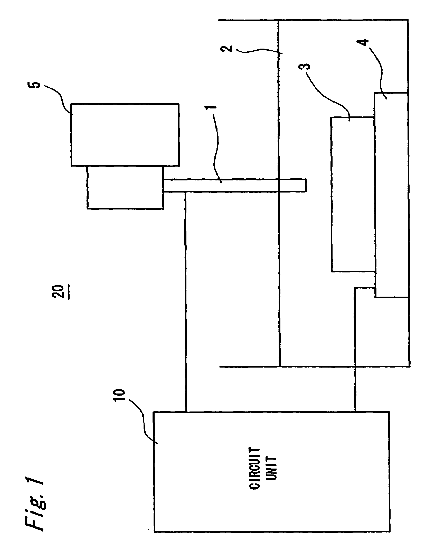
[0054]FIG. 1 shows a schematic configuration of an electrical discharge machining apparatus 20 according to a first embodiment of the invention. The electrical discharge machining apparatus 20 includes a tool electrode 1, a drive unit 5 that vertically moves the tool electrode 1, a work (work piece) electrode 4 that supports a work 3 made of metal and the like immersed in a working fluid 2, and a circuit unit 10 that is electrically connected to the tool electrode 1 and the work electrode 4. The work 3 is placed and fixed onto the work electrode 4. The tool electrode 1 is located opposing the work electrode 4 with a predetermined gap therebetween. The work 3 and at least a leading end portion of the tool electrode 1 are immersed in the working fluid 2 such as deionized water having relatively high insulating characteristics. Then, the gap between the tool electrode 1 and the work 3 is filled with the working fluid 2. When a potential difference or a distance between the tool electro...

second embodiment

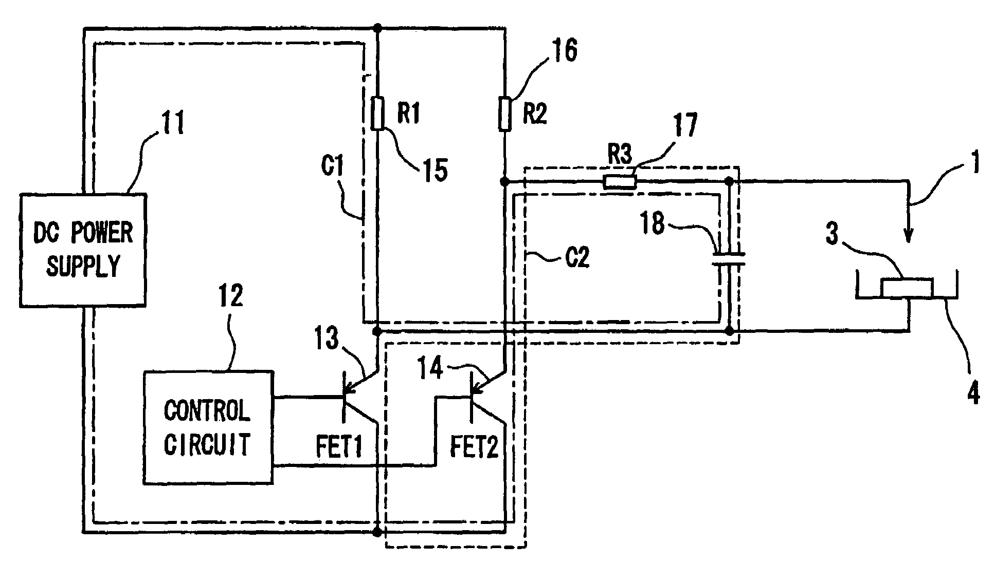
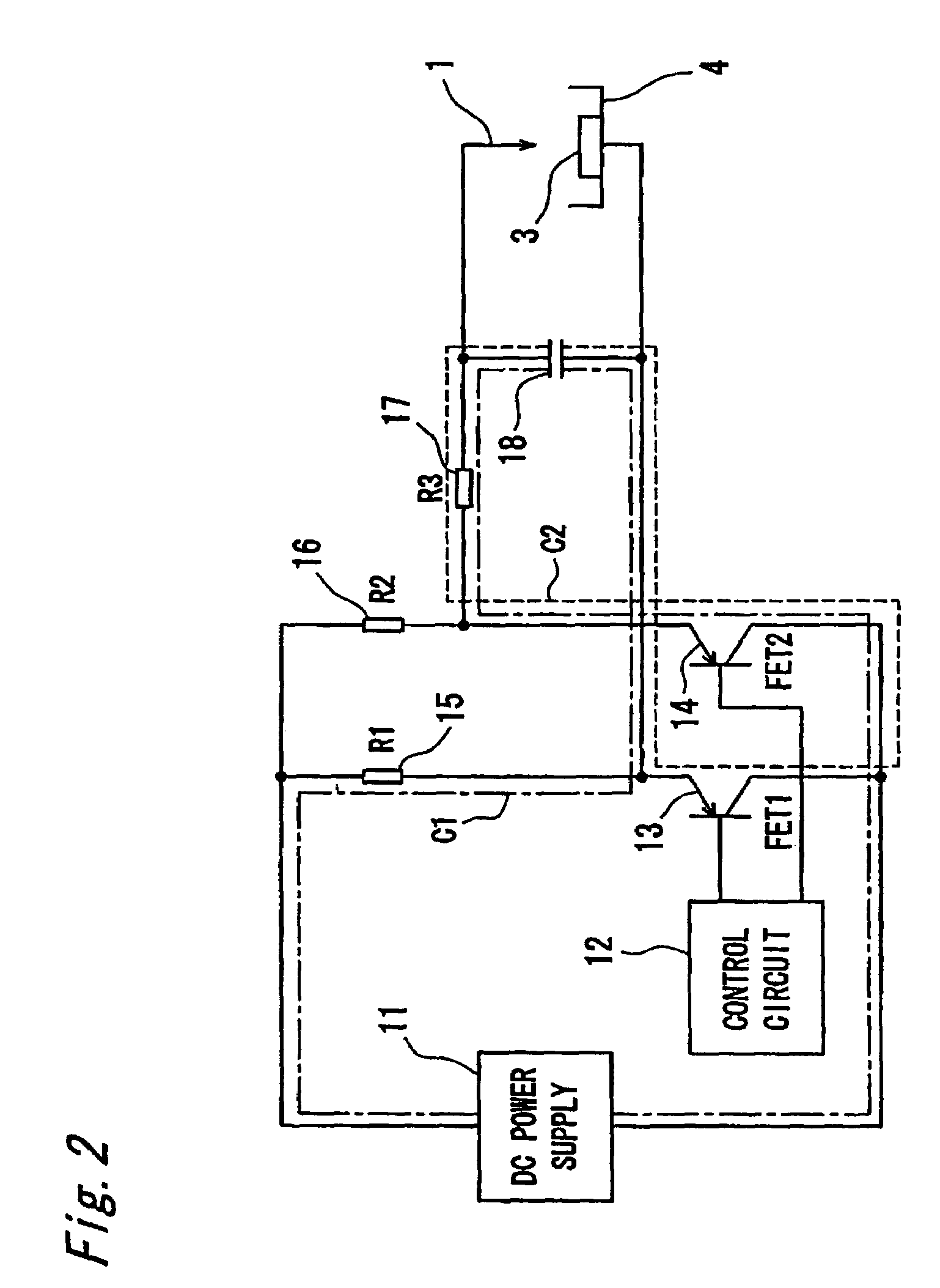
[0074]FIG. 10 is a schematic view showing a circuit configuration of an electrical discharge machining apparatus according to a second embodiment of the invention. As shown in FIG. 10, the electrical discharge machining apparatus according to the second embodiment differs from the electrical discharge machining apparatus according to the first embodiment in the configuration of a circuit unit 10a. The circuit unit 10a differs in that the circuit unit 10a includes a current detector 19a that detects the current passing between the tool electrode 1 and the work electrode 4, and a voltage detector 19b that detects the voltage applied between the tool electrode 1 and the work electrode 4. The current detector 19a and the voltage detector 19b are connected to a control unit 12a, and measured voltage data and current data are inputted to the control unit 12a. The capacitor 18 is charged by applying the voltage outputted from the direct-current power supply 11 (DC power supply) constitutin...

third embodiment

[0123]The case in which the electrical discharge machining of a metal plate 100 is performed to make a through-pore by adopting the electrical discharge machining method according to the invention will be described with reference to FIGS. 18 and 19. FIG. 18 is a sectional view of the metal plate 100 that has oxide films 101 and 102 on its surfaces. In this case, it is assumed that the portions that are oxidized on the surfaces of the metal plate 100 are the oxide films 101 and 102 and the portion that is not oxidized is a metal portion 103.

[0124]FIG. 19A is a timing chart of the voltage pulse applied between the tool electrode 1 and the work electrode 4. FIG. 19B shows the case in which the electrical discharge is detected for the applied voltage pulse. FIG. 19C shows the case in which the conduction is detected for the applied voltage pulse. The portions represented by zones A1 and A2 show the machining of the oxide film 101, the portions represented by zones B1, B2, and B3 show th...


PUM

PropertyMeasurementUnit
diameteraaaaaaaaaa
peak voltagesaaaaaaaaaa
currentaaaaaaaaaa

Abstract

An electrical discharge machining apparatus includes a work electrode adapted to support a work immersed in a working fluid, a tool electrode located opposing the work electrode with a predetermined gap therebetween, a capacitor that is connected between the work electrode and the tool electrode to provide a series of voltage pulses, a charging circuit having a power supply and a first switching element which are connected in series to the capacitor, a charge regulating circuit having a second switching element connected in series to the capacitor, and a control unit that controls the first and second switching elements, such that the first switching element turns on, and then the second switching element turns on before the first switching element turns off. Then, one voltage pulse, having a leading edge corresponding to the turning on of the first switching element and a trailing edge corresponding to the turning on of the second switching element, is generated.

Description

BACKGROUND OF THE INVENTION[0001]1. Field of the Invention[0002]The present invention relates to a machining apparatus and a machining method in which a work is machined by applying voltage to a microscopic gap between a tool electrode and the work to utilize electrical discharge or an electrolytic reaction generated in the gap. More particularly, the present invention relates to an electrical discharge machining method and an electrical discharge machining apparatus that are used for fine machining for forming a microscopic pore, a microscopic hole, a microscopic slit, or the like.[0003]2. Description of the Related Art[0004]Conventionally, the micro electrical discharge machining technology is mainly used as the method of machining a microscopic pore and a microscopic hole, for example, machining a nozzle of an inkjet printer. Recently, an ultra-fine electrical discharge machining apparatus has been developed that can make the hole have a minimum diameter up to 5 μm.[0005]FIG. 20 ...

Claims


Application Information

Patent Timeline
Patent Type & Authority Patents(United States)
IPC IPC(8): B23H1/02B23H7/14B23H9/14
CPCB23H1/022B23H9/14
Inventor HIRAISHI, MASAKAZUMURO, MASAHIROMASAKI, TAKESHIWADA, TOSHIHIKO
Owner PANASONIC CORP
Why Eureka
Try Eureka